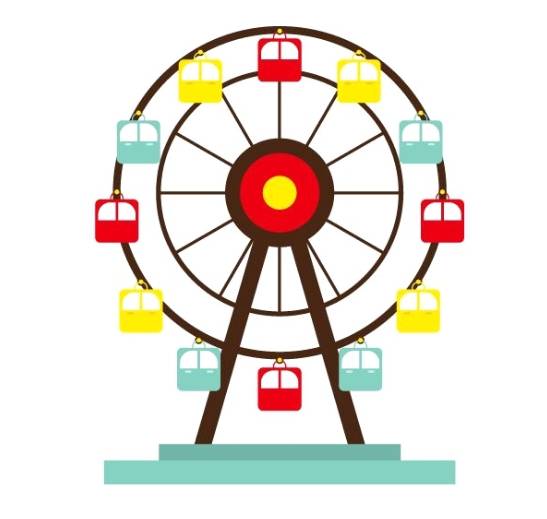
Ferris wheel is a very popular amusement facility in some amusement parks and large parks on Earth. It is a large wheel-shaped mechanical construction facility, with a cockpit hanging on the edge of the wheel for passengers to ride on, and as the wheel slowly rotates, passengers can enjoy the surrounding scenery from different heights. In order to let the inhabitants of Planet M also be able to enjoy the happiness brought by the Ferris wheel, the designers of the Maker Factory started to design a Ferris wheel for the amusement park of Planet M. The designers of the Ferris wheel were very enthusiastic about the idea of a Ferris wheel.
Determine the design
Analyze the works
The various Ferris wheels on Earth provide us with abundant samples, so we only need to refer to one of them, observe what a Ferris wheel looks like and what its components are, and then, transform it into our own design.
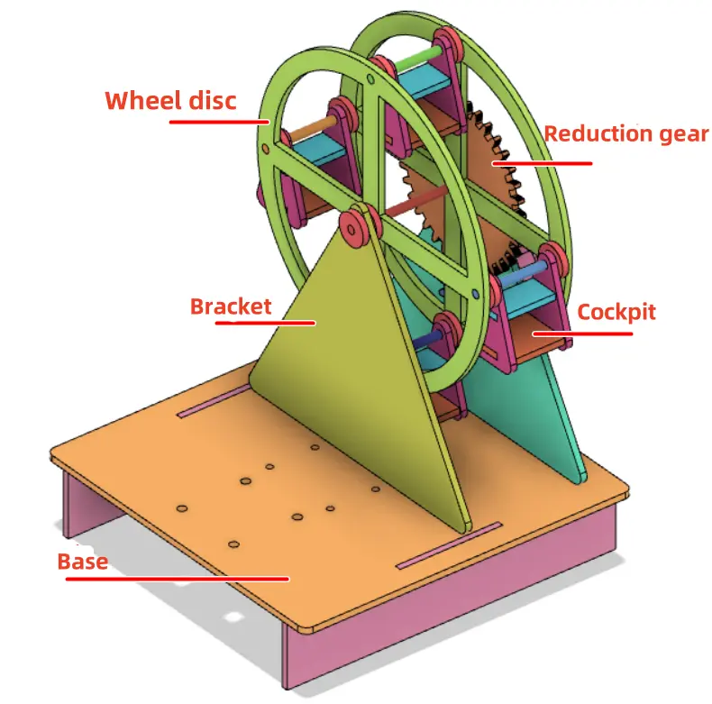
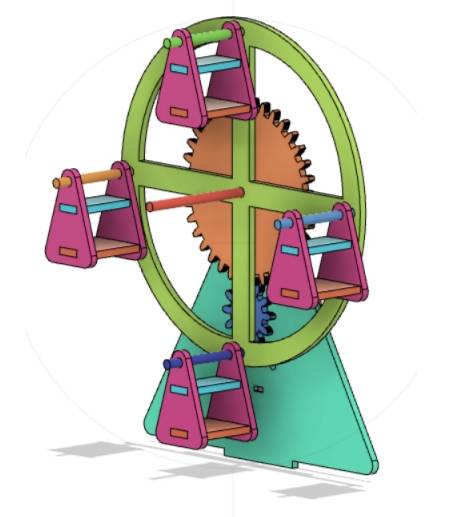
In terms of appearance, the Ferris wheel consists of a rotating wheel, a cockpit suspended from the wheel, a stand to support the wheel, a power unit to rotate the wheel, and a base cockpit to hold the stand in place.
Equipment list
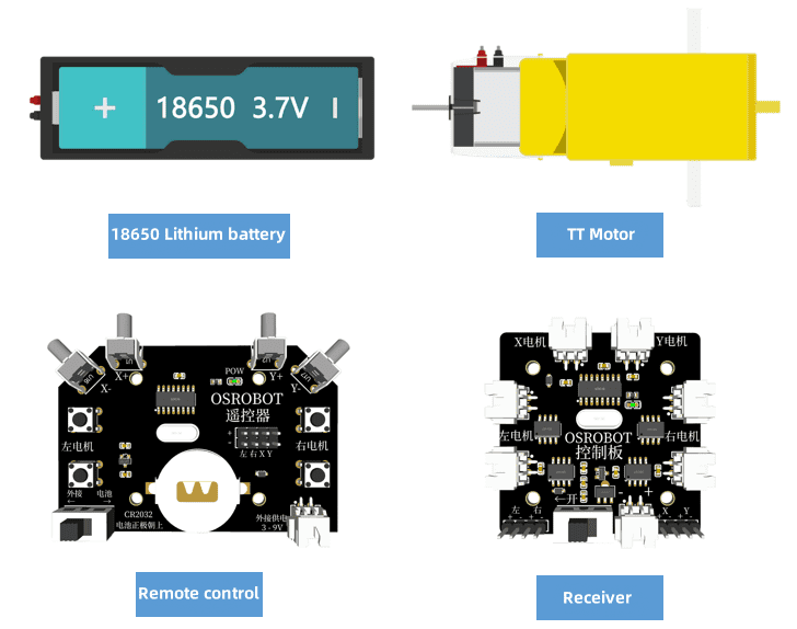
After a preliminary analysis to determine the basic components of the Ferris wheel, next, we can find the right materials to make it according to the components. By disassembling and analyzing each part of the Ferris wheel and combining it with the available materials in the object factory, we can determine the following equipment list:
No.
Name
Quantity
1
2.4G remote control (with battery)
1
2
2.4G Receiver
1
3
TT motor (1:220)
1
4
18650 Battery (with cable)
1
5
Basswood Laminate (40cm*60cm*3mm)
1
6
M3 screws and nuts, copper posts
Several
7
4mm wooden rods
A number of
Structural Design
In order for the Ferris wheel to function properly, structural design is a top priority.
Build the parts list
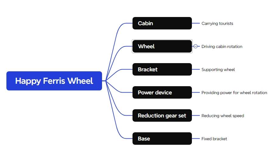
According to the structural analysis of the Ferris wheel and the list of equipment, we can determine the works need to design the structure of the parts table, the works of the design of the structure of the parts have a total of five parts.
Part number
Part name
Number of parts
Function
1
Cockpit
4
Carries tourists
2
Wheel
2
Turning the cockpit
3
Reduction gear set
1
Reduces the rotation of the disk
4
Bracket
2
Connects the wheel to the base and holds the motor
5
Chassis
1
Fixing bracket, battery box, receiver
Laser Modeling
With the parts list as a reference, we can straighten out our thoughts and start laser modeling.
1.Drawing the bracket
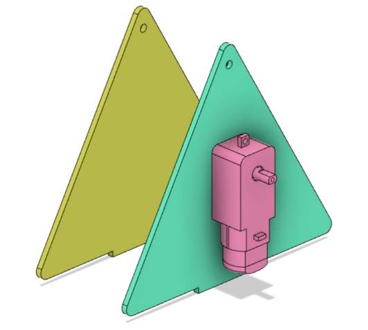
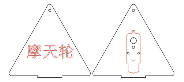
The bracket is an important part of the Ferris wheel, combined with the effect diagram, we use the structure of the triangle.
(1) Adjusting the “TT Motor” Graphic
In order to make the structure of the Ferris wheel more compact, the size of the stand can be roughly determined by the size of the TT motor. As shown in the figure below, the TT motor is fixed on the bracket.
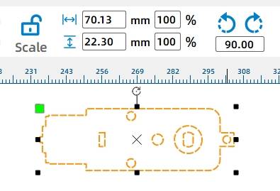
Open LaserMaker, from the Gallery [9. Open Source Robotics Hardware], select the “TT motor” graphic, drag and drop it to the canvas, check the dimensions of the TT motor, and right-click on the “TT motor” graphic, use the group function to combine the graphics.
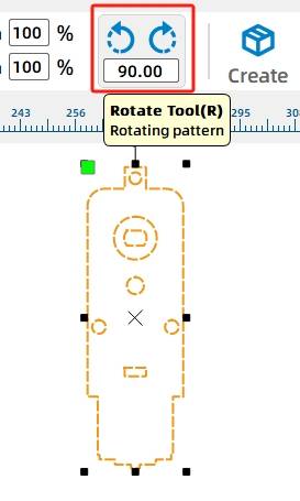
Select the “TT motor” graphic, the mouse pointer near the graphic above the rotation icon, the use of the [Rotate] function, the TT motor rotated 270 °.
(2) Determine the position of the TT motor
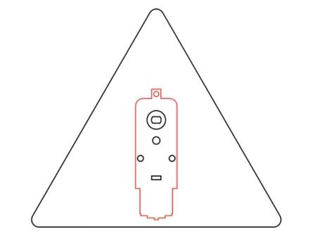
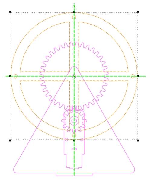
From the Gallery [Basic Graphics] in the “triangle” drag and drop to the canvas, adjust the size of the triangle (isometric adjustment of width and height), and the TT motor size comparison, roughly determine the size of the triangle for the width of 140mm, 121.24mm high, in order to make the bracket is more beautiful, we can use the [Drawing Box] of the [Rounding Tool 】 on the triangle for rounded corners (corner radius of 4mm), the TT motor drag and drop to the appropriate position of the bracket, using the [Drawing Box] of the [Alignment Tool] of the “horizontal center alignment” will be aligned with the two, the following chart.
(3) Drawing the tenon of the bracket
Using the [Drawing Box] of the [Rectangle Tool], draw a rectangle 40mm wide and 3mm high as the tenon of the bracket, drag the rectangle, align the upper edge of the rectangle with the lower edge of the triangle, select the rectangle and the triangle, use the [Drawing Box] of the [Align Tool] of the “Horizontal Center Align” will be the two aligned, and then use the [Drawing Box] of the [Concatenate] tool will be the two aligned. [Drawing Box] of the [and set] tool will be merged together to form the prototype of the Ferris wheel bracket.
2. Draw the reduction gear
Ferris wheel in the process of running, in order to allow visitors to have a more comfortable experience, its rotation is usually slower, therefore, in the design of the Ferris wheel, we also need to consider the problem of wheel speed, in addition to the use of a single 18650 battery, the use of higher reduction ratio of the motor, the design of the reduction gear set is also an effective means to reduce the speed of the wheel.
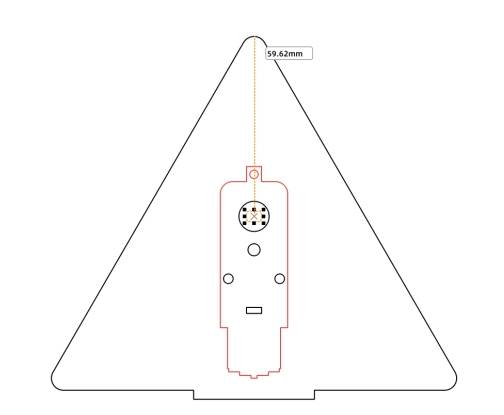
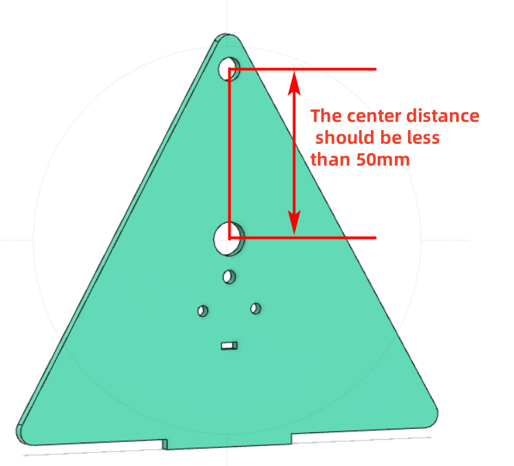
(1) Determine the center distance of the reduction gear
Use the [Distance Measuring Tool] measuring tool in the [Drawing Box] to measure the distance from the center of the TT motor shaft to the top of the bracket as 59.62mm. In actual measurements, this distance is related to the position where the TT motor is placed, and the actual distance prevails.
Since the axle of the wheel and gear is made of a 4mm diameter wooden stick, and considering that the axle cannot be too close to the upper edge of the bracket, combined with the previous step of measuring the distance from the center of the TT motor shaft to the top of the bracket as shown in the figure below, the center distance between the two holes should be less than 50mm as appropriate.
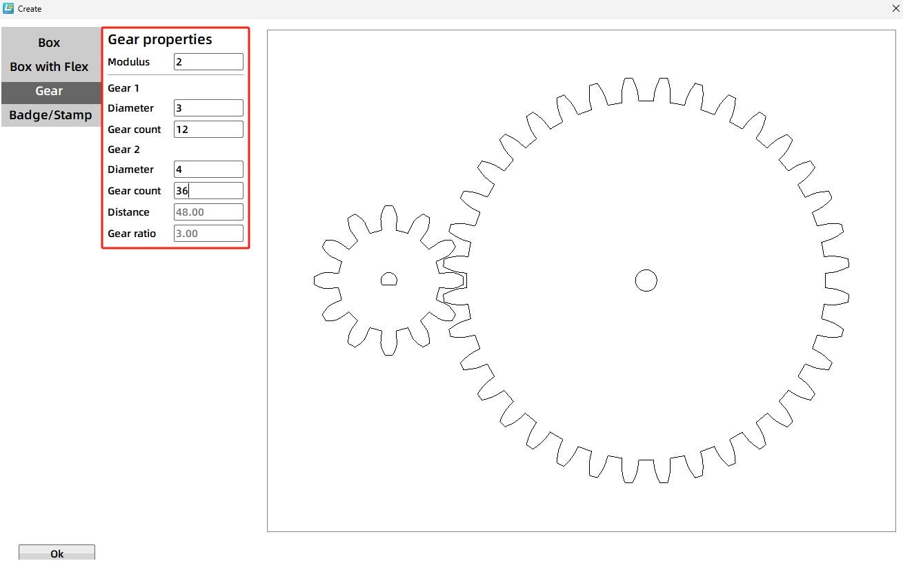
(2) Drawing modulus gear
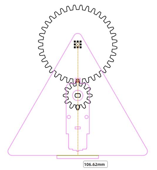
Click the [toolbar] in the [artifact] tool, select the modulus gear, gear parameters are set to: modulus 2, gear 1 (bearing diameter 3mm, the number of gears 12), gear 2 (bearing diameter 4mm, the number of gears 36), the center distance is automatically confirmed to be 48mm, in line with the bracket on the center distance of the gear reducer set of the requirements, click OK to get the gear reducer set.
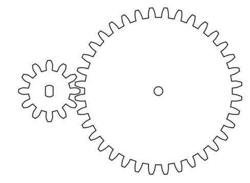
(3) Adjusting the modulus gear
Since the TT motor shaft does not match the D-shaped hole position of the modular gear, it is necessary to change the D-shaped hole position to that of the TT motor. Select the gear 1 D-shaped holes to delete, from the Gallery [Open Source Robotics] in the selection of “TT motor hole” graphics, drag and drop to the canvas, using the [Drawing Box] of the [Alignment Tools] of the “Horizontal Center Alignment” and “Vertical Align the two using the “Horizontal Center Align” and “Vertical Center Align” of the [Alignment Tool] in the [Drawing Box]. In order to prevent the installation of gears due to the gear mesh closely caused by the jamming, we can select the gear 1, move it to the left 1mm (X coordinate minus 1), that is, to complete the drawing of the reduction gear set, the final effect is shown below.
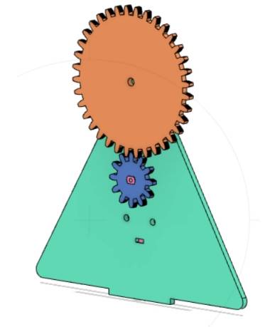
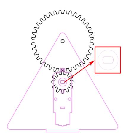
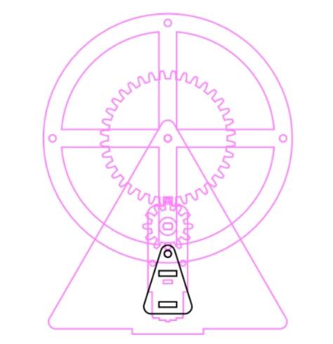
(4) Determine the position of the reduction gear group
Select the two gears, use the [Rotate] tool to rotate them by 270°, right-click and select the group function to combine the two. Drag the two gears to the bracket, so that the TT hole position of the gears and the TT hole position on the bracket overlap, in order to determine the position of the reduction gear set, this time, the hole of gear 2 can also be used as a 4mm shaft hole on the bracket, as shown below, the location of the shaft hole is relatively reasonable.
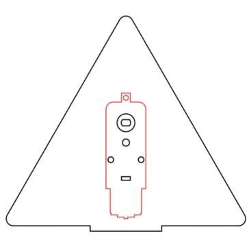
(5) Duplicate the final bracket
Select the stent outline and the shaft hole, right-click to copy, paste to get a piece of the stent, use the text tool to label the Ferris wheel, the layer is set to red; and then select the stent outline, the TT motor graphics and the shaft hole, right-click to copy, paste to get another piece of the stent.
3. Draw the wheel
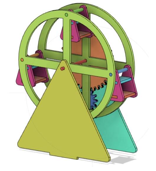
The wheel is a key component of the Ferris wheel, its rotation drives the cockpit rotation, which allows people to see a more beautiful scenery, as shown in the figure, the two green circular parts for the wheel.
(1) Measure the distance from the center of the wheel’s shaft to the bottom of the stand.
In order to ensure that the cockpit will not touch the bottom when the wheel is rotating, we need to measure the size of the bracket before designing the wheel and cockpit.
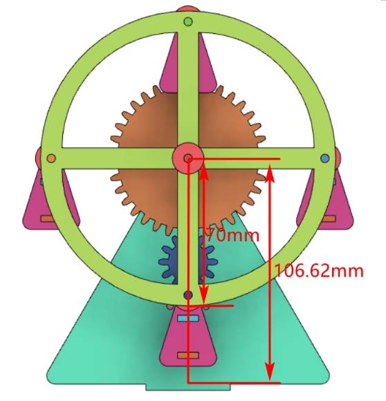
Use [Line Tool] in [Drawing Box] to connect the two points above the tenon and draw a dark green line segment as an auxiliary line to assist the measurement; use [Distance Measuring Tool] in [Drawing Box] to measure the distance from the axle hole in the bracket to the bottom side of the bracket as 106.62mm.
(2) Drawing the outline of the wheel disk
In order to make the size of the Ferris wheel and the cockpit more coordinated, according to the distance measured in the previous step, we can set the radius of the wheel to 70mm, that is, the diameter of the wheel is 140mm.
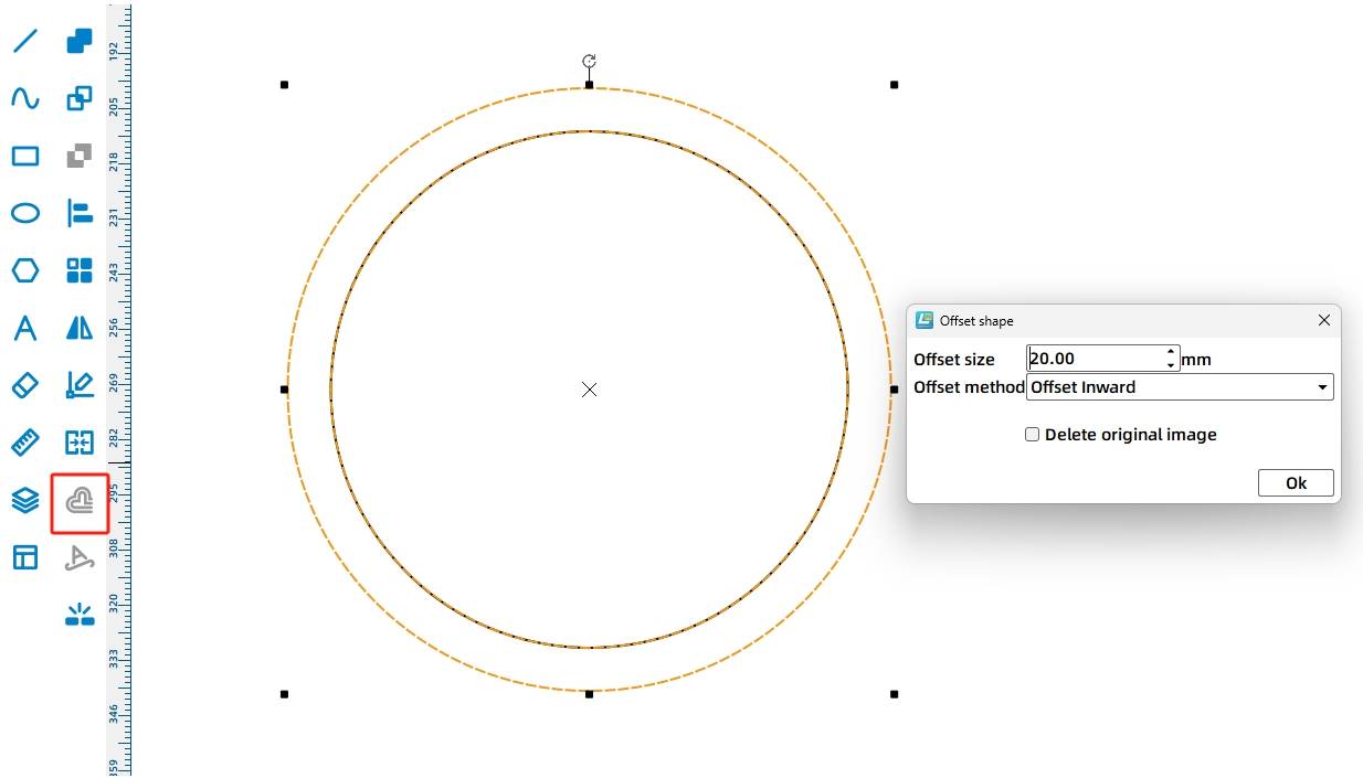
Using the [Drawing Box] in the [Ellipse] tool to draw a circle with a diameter of 140mm, select the circle, and then use the [Drawing Box] in the [Offset Curve] tool, offset size of 20mm, offset mode for the inner offset, click OK, to get a set of concentric circles.
(3) Drawing the inner contour of the disk
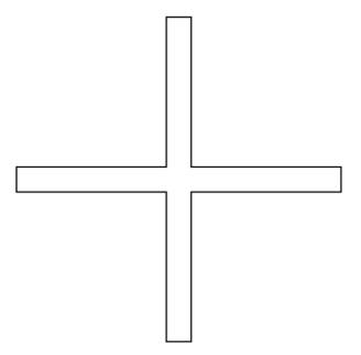
Using the [Drawing Box] in the [Rectangle] tool to draw a width of 130mm, 10mm high rectangle, right-click, copy a copy, rotate it 90 °, and then, using the [Drawing Box] in the [Alignment Tool] of the “Horizontal Center Alignment” and “Vertical Center Alignment “tool will be aligned with the two rectangles, the use of [Drawing Box] in the [and set] tool, the two rectangles will be merged to get a hollow ‘ten’.
(4) the prototype of the wheel
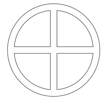
Drawing Box] in the use of [Alignment Tools] of the “horizontal center alignment” and “vertical center alignment” tool will be “ten” and concentric circles aligned, selected “Ten” word, the use of [Drawing Box] in the [Difference Set] tool, take the difference set, you can get the prototype of the wheel, set its coordinates to (300,100).
(5) drawing cockpit hole
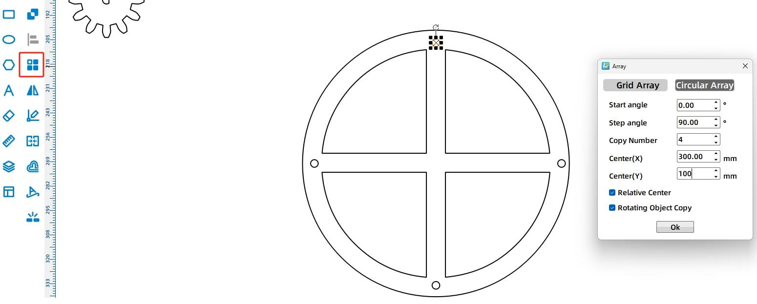
Using the [Drawing Box] in the [Ellipse] tool to draw a circle of 4mm in diameter, move to the upper edge of the disk in a suitable position as the cockpit axis hole. Select the circle, use the [Drawing Box] in the [Array] in the ring array tool, start angle 0 °, step angle of 90 °, the number of copies of 4, the center point (300,100), rotate the object copy, to determine, to get the final roulette wheel, select the roulette wheel of all the graphics, click the right button, the use of the group tool to combine them.
(6) determine the location of the wheel
Drag and drop the wheel so that the center of the wheel is centered and aligned with the axle holes on the bracket to determine the position of the wheel. Since, the bracket and the wheel are connected by the same 4mm stick, at this point, the 4mm axle holes on the bracket can also be used as axle holes for the wheel.
4. Draw the cockpit
(1) Determine the height of the cockpit
In order to ensure the smooth operation of the Ferris wheel, the movement of the cockpit to the bottom of the time, can not touch the bottom, before drawing the cockpit, first through the measurement, to determine the height of the cockpit.
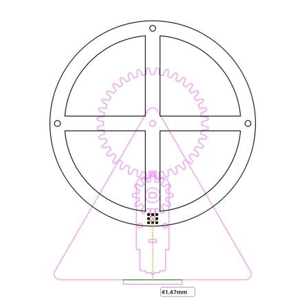
Using the [Drawing Box] in the [Distance Measuring Tool], measuring the lowest hole in the wheel to the base of the distance of 41.47mm, the size of the reference, to determine the height of the cockpit is best not to exceed 41mm; measurement is complete, you can select the dark green auxiliary line, press the DEL key to delete it.
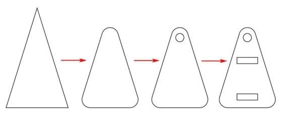
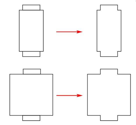
(2) Drawing cockpit side
From the gallery [basic graphics] in the “triangle” drag and drop to the canvas, the size will be modified to width 30mm, height 48mm. using [Drawing Box] in the [Corner Tool] on the three corners of the rounding operation, rounded radius of 4mm. using [Drawing Box] in the [Ellipse Tool] to draw a 4mm diameter circle as the axle hole, drag to the appropriate location, press the DEL button to delete it. axis hole, drag and drop to the appropriate location. Use [Drawing Box] in the [Rectangle Tool] to draw two rectangles 10mm wide and 3mm high as the base of the cockpit and the roof of the eye, drag and drop to the appropriate position of the horizontal center alignment, the formation of the side of the cockpit.
(3) Drawing the cockpit roof and cockpit base
Use the [Drawing Box] in the [Rectangle Tool] to draw a rectangle 14mm wide and 24mm high as the main body of the cockpit roof, use the [Drawing Box] in the [Rectangle Tool] to draw two rectangles 10.1mm wide and 3mm high as the tenons of the cockpit roof, drag and drop the two tenon rectangles to the top and bottom of the cockpit roof rectangles, respectively, with the top and bottom of the cockpit roof rectangles, and horizontally centered alignment, then, use the [Drawing Box] to draw the cockpit roof and base of the cockpit. Align the two tenon rectangles with the top and bottom of the cockpit roof rectangle, and center them horizontally. Then, use the Merge Tool in the Drawing Box to merge the three rectangles to form the cockpit roof.
Use the Rectangle Tool in the Drawing Box to draw a rectangle with a width of 25mm and a height of 24mm as the main body of the cockpit base, and use the same operation as above to draw the base of the cockpit.
(4) Determine the position of the cockpit when it reaches the bottom.
Select all the graphics on the side of the cockpit, right-click, use the group function to combine them, drag the side of the cockpit to the position of the wheel, so that the cockpit axle holes are aligned with the cockpit axle holes on the wheel, to determine the position of the cockpit to the bottom of the movement, as can be seen in the figure below, the cockpit will not touch the bottom.
(5) Duplicate all the parts of the cockpit.
In the design of the Ferris wheel, the use of four cockpits, each cockpit consists of two cockpit side, a cockpit roof and a cockpit base, which can be calculated, the final number of parts of the four cockpits are: cockpit side 8, cockpit roof 4, cockpit base 4.
Select the cockpit sides, cockpit roof and cockpit base, and copy all the parts according to the above quantities.
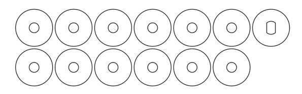
(6) Drawing gaskets
In order to ensure that the Ferris wheel can run smoothly, we need to add shims between the wheel and the bracket, wheel and cockpit, of which there are 4 between the wheel and the bracket, 8 between the wheel and the cockpit, a total of 12; In addition, due to the increase of shims at the wheel and the bracket, the TT motor shaft and pinion connection needs to be increased by 1 shim.
Using the [Drawing Box] in the [Ellipse Tool] were drawn with a diameter of 4mm and a diameter of 15mm circle, the use of [Drawing Box] in the [Alignment Tool] of the “horizontal center alignment” function and “vertical center alignment” function will be aligned, forming a Concentric circles are used as spacers for the wheel and cockpit shafts. Select the shims, right-click, and duplicate them to get 12 shims.
Use [Drawing Box] in the [Ellipse Tool] to draw a circle with a diameter of 15mm, select the “TT motor hole” graphic from the Gallery [Open Source Robotics], drag and drop it to the canvas, and use the [Drawing Box] in the [Alignment Tool] “Horizontal center alignment” function and “Vertical center alignment” function to align the circle with the “TT motor hole” to get the spacer of the TT motor shaft. function and “Vertical Center Align” function in the [Drawing Box], align the circle with the “TT motor hole” to get the spacer of the TT motor shaft.
5. Draw the base
(1) Determine the position of the eye of the bracket.
Ferris wheel bracket is fixed on top of the base, so before drawing the base, we first need to determine the location of the bracket eye.
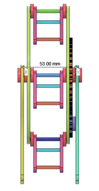
In the cockpit base and roof drawing, we can determine the cockpit width of 30mm, plus the cockpit on both sides of the spacer, can calculate the interval between the two discs for 36mm, plus the thickness of the two discs 6mm, plus the thickness of the gears 3mm and the thickness of the gear shims 3mm, as well as the other side of the disc of the thickness of the gasket 3mm, you can determine the spacing between the stent distance of 51mm. In order to allow the wheel and cockpit to rotate smoothly, the distance between the brackets should be slightly larger than the theoretical distance, so the distance between the bracket eyelets is set to 53mm.
(2) Drawing the brace mortise
Since the bracket mortise and tenon is 40mm wide and 3mm high, in order for the bracket to be more tightly embedded in the base, the size of the mortise and tenon should be slightly smaller than the size of the mortise and tenon.
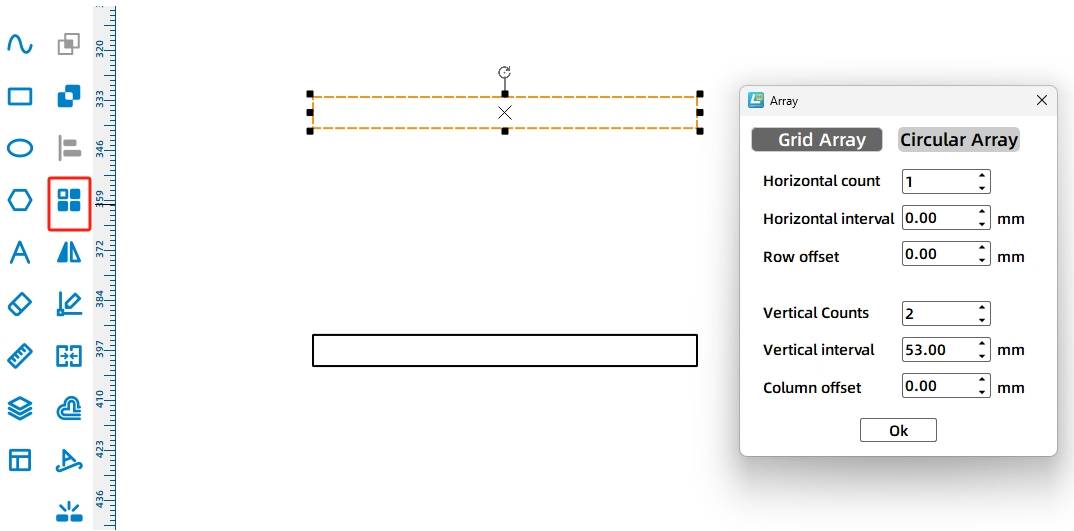
The use of [Drawing Box] in the [Rectangle Tool] draw a 39.5mm wide, 3mm high rectangle, click the tool menu bar in the [Rectangle Array] tool, set the parameters in the pop-up window: the number of horizontal 1, the number of vertical 2, the vertical spacing of 53mm, offset 0mm, click OK, you can get the two bracket eye.
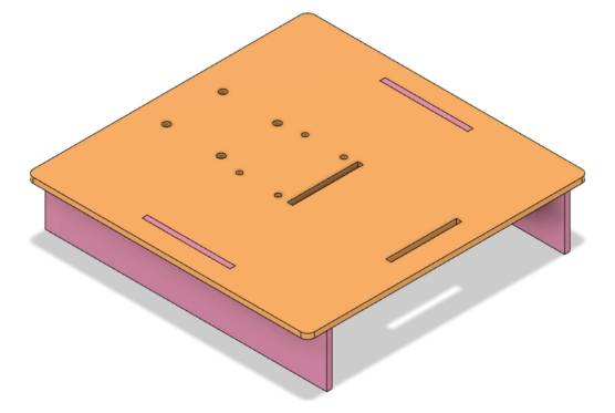
(2) Drawing the base plane
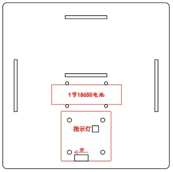
The base plane in addition to fixing the bracket, but also need to fix the 18650 battery and OSROBOT control board, therefore, we need to plan their positions on the base plane.
From the LaserMaker Gallery, select “18650 Battery Tie-down” in the “Open Source Robotics” option, and drag it to the bottom of the bracket eyelet position.
From the LaserMaker Gallery, select “OSBOBOT2 Control Panel (sunken)” from the “Open Source Robotics” option and drag and drop it underneath the 18650 battery location.
Combine the bracket eyelet position and bracket dimensions to make a simple layout, and roughly determine the size of the base platform as 160mm*160mm.
Use the [Rectangle Tool] in the [Drawing Box] to draw a square with a width of 160mm and a height of 160mm as the prototype of the base plane. Use the Round Corner Tool in the Drawing Box to round the corners of the rectangle with a radius of 4mm.
Since both the 18650 battery and the OSBOBOT2 control board are fixed underneath the base plane, the base plane also needs two brackets.
Use the [Drawing Box] in the [Rectangle Tool] to draw two rectangles 3mm wide and 50mm high as the eye of the base bracket, drag and drop them to the base plane at the appropriate location.
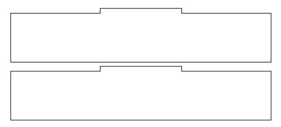
(3) Draw the base bracket.
According to the size of the 18650 battery, we can set the height of the base bracket to 30mm.
Use the [Drawing Box] in the [Rectangle Tool] to draw a rectangle 160mm wide and 30mm high as the prototype of the base bracket, and draw a rectangle 40mm wide and 3mm high as the tenon of the base bracket. Drag and drop the tenon of the base bracket to align it with the top side of the rectangle and center it horizontally. Use the [Drawing Box] in the [Merge Tool] to merge the two, you can get to the base bracket. Select the base bracket, right-click and then copy one, you can get all the base bracket.
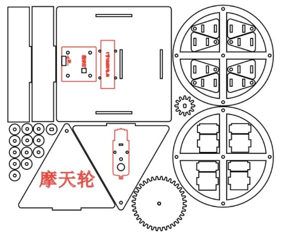
6. Layout
Laser Processing
Setting parameters
(1) Trace the line
Double-click the red block in the processing process area, the processing parameters of the material selection 1. basswood plywood, processing process selection tracing line, processing thickness selection 0.10, click OK.
(2) cutting
Double-click the black block in the processing area, select 1. basswood plywood for the material of the processing parameters, select the cutting process, select the processing thickness of 3.00, click OK.
Start building things
Turn on the laser cutting machine power switch, turn on the laser switch, wait until the start building button becomes blue, click start building, wait until the drawing is uploaded to the laser cutting machine, click the start button of the laser cutting machine panel, start cutting.
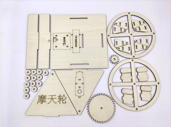
Assemble the model
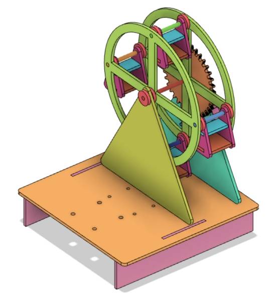
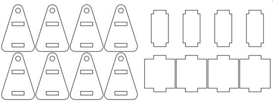
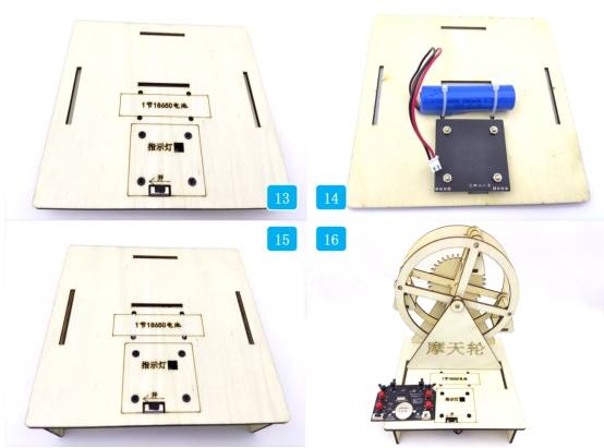
The physical picture of the finished cutting in the artifact project is as follows:
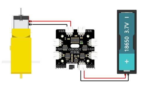
Circuit Wiring
In order to make the Ferris wheel work smoothly, the playground staff can refer to the following diagram for circuit connection.
Structural Assembly
We assemble the model according to the following steps:
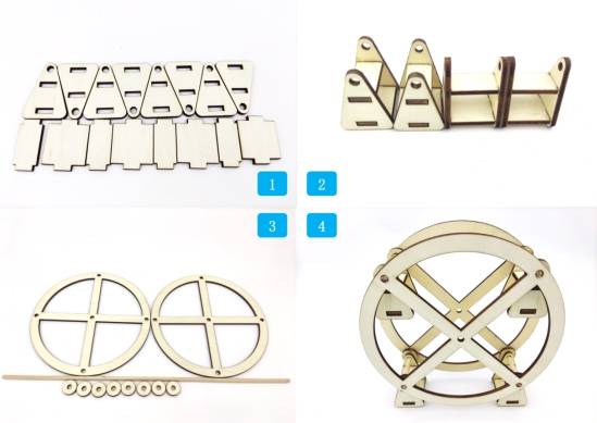
The first step is to find the relevant parts of the cockpit.
Step 2, assemble the 4 cockpits.
Step 3, find the related parts of the wheel.
Step 4, assemble the cockpit and the wheel with a 4mm wooden stick and spacers. The edge of the wooden stick is glued with hot melt glue to the hole of the cockpit shaft of the wheel, and a little gap is kept between the two pieces of the wheel and the cockpit to ensure that the cockpit can always hang down when the wheel is rotating.
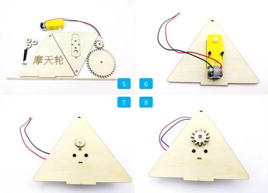
Step 5, locate the reduction gear set, bracket TT motor and other related parts.
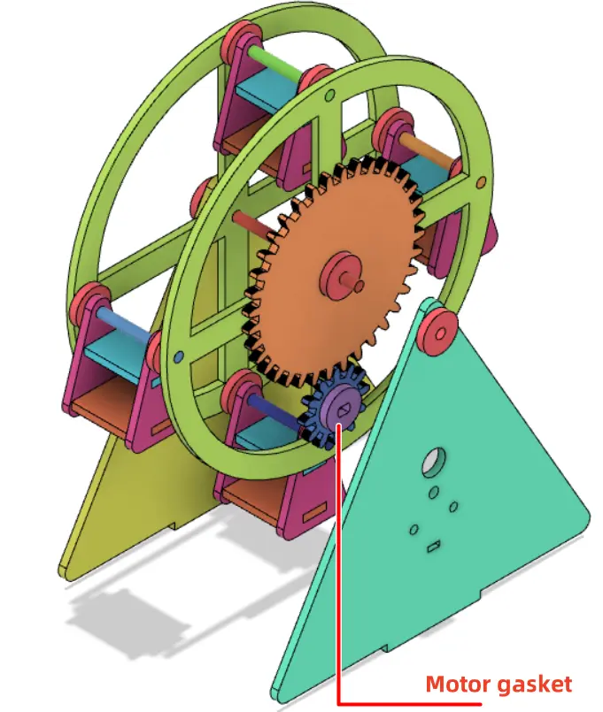
Step 6, secure the TT motor to the bracket with screws and nuts.
Step 7, install the spacer onto the TT motor shaft.
Step 8, install the pinion gear to the TT motor shaft.
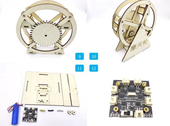
Step 9, align the large gear shaft hole with the wheel shaft hole and glue together.
Step 10, string the wheel disk to the bracket with a 4mm wooden stick.
Step 11, locate the base, OSBOBOT receiver plate, copper post, screws, nuts and other parts.
Step 12, fix the copper post to the OSROBOT2 control board.
Step thirteen, fix the OSROBOT2 control board to the base.
Step 14 Secure the battery to the base bracket with tie wraps.
Step 15, attach the base bracket.
Step 16, fix the bracket to the base, add spacers on both sides of the wheel axle and fix it with hot melt glue.
Summarize
In the completion of this work in this work, we used gear transmission to design and produce a happy Ferris wheel, in the process of design, we used the modulus gear function of the one-button build to draw a reduction gear set, and in the process of laser cutting, we further familiarized ourselves with the processing of laser cutting. During the design, processing and production of the work, we had a complete experience of the whole process from design drawings to physical production, and we also successfully completed the order of the ferris wheel for the amusement park of Planet M.
Thinking Expansion
The ferris wheel model designed and produced in this project basically realizes the basic functions of the ferris wheel, can we continue to improve it? For example, increase the number of cockpits and continue to reduce the rotation speed of the Ferris wheel through multiple gears.


.png "laser cutter Globle")


