The ring toss game in amusement parks always draws the attention of both children and adults. If a player successfully lands a ring on a gift, they can take it home. However, this seemingly simple game is actually quite challenging. Players need to maintain their physical balance while strategizing the angle and force of their throw.
Let’s take a look at the ring toss game device designed for Planet M.
Determining the Design Plan
Analyzing the Work
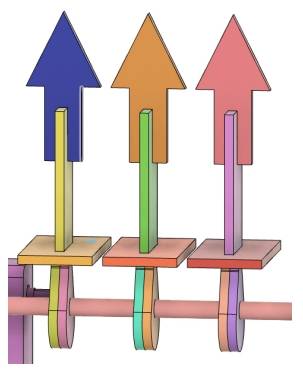
The common ring toss game in our daily lives involves players using rings to land on dolls or other prizes. We can add more challenges to this by varying the ring size, increasing the throwing distance, or changing the position of the gifts. For instance, the gift positions can be changed using the OSROBOT remote control kit, allowing players on Planet M to aim at moving gifts to win their corresponding prizes. As shown in the following figure.
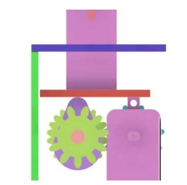
In previous projects, designers have used remote control kits to control TT motors to make objects move in a circular motion. This time, we can utilize a cam device to vary the movement trajectory. Specifically, the motor will control the cam to rotate in a circular motion, which will then drive the gift holder to move in a straight line. As illustrated in the following figure.
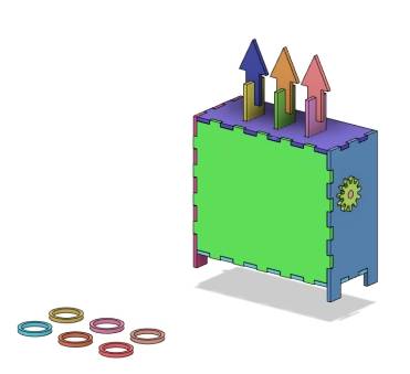
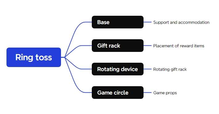
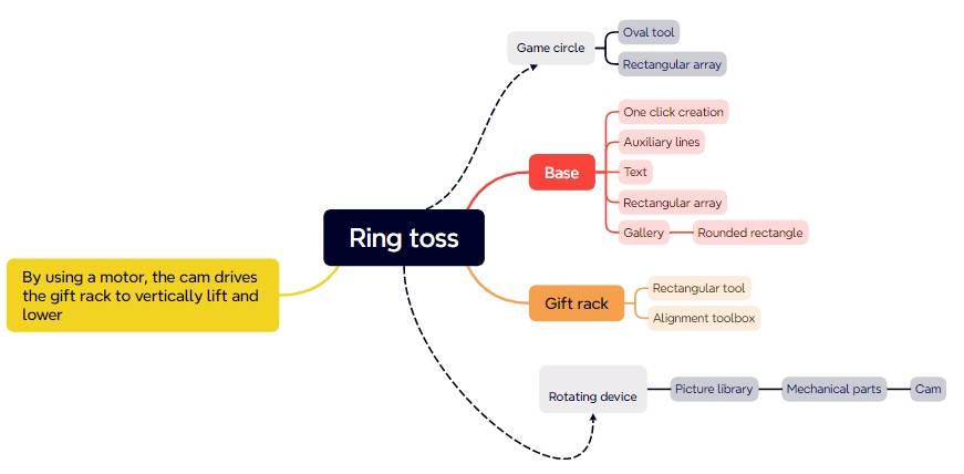
After careful analysis, we can break down the ring toss game device into a base, gift holder, rotating mechanism, and game rings. As shown in the following figure.
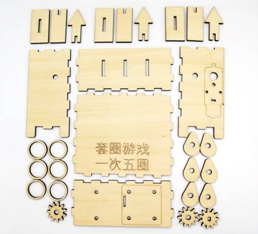
Materials List
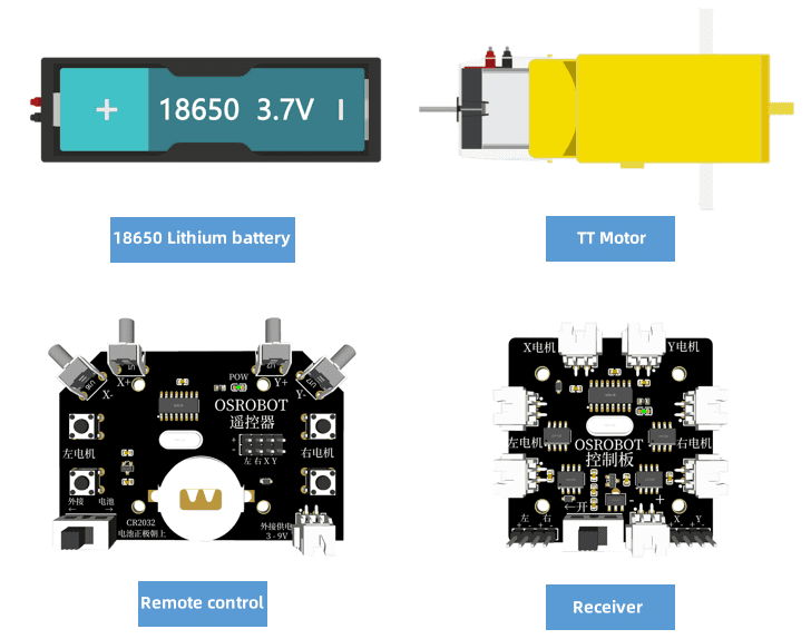
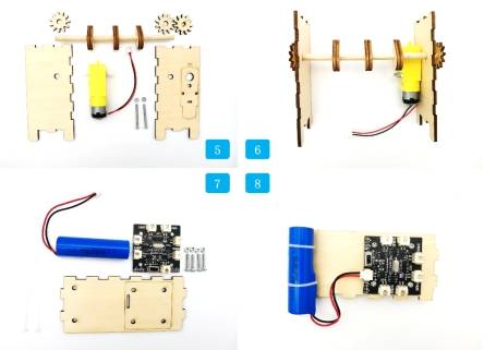
Next, we need to compile a list of required materials based on our needs and gather them from the makerspace accordingly. See the following table and figure for details.
No.
Name
Quantity
1
2.4G Remote Control (with battery)
1
2
2.4G Receiver
1
3
TT Motor (1:120)
1
4
18650 Battery (with wire)
1
5
Basswood Plywood (40cm60cm3mm)
1
6
M3 Screws and Nuts
Several
7
Wooden Rod with 6mm Diameter
1 piece
Structural Design of the Project
Creating a Parts List
With the materials for the ring toss game device prepared, we can complete the exterior structural parts list as shown in the following table.
Part No.
Part Name
Quantity
Function
1
Base
4
Secures the brackets, battery box, and receiver
2
Gift Holder
9
Holds the gifts
3
Rotating Mechanism
8
Moves the gift holder up and down
4
Game Rings
5
Game props
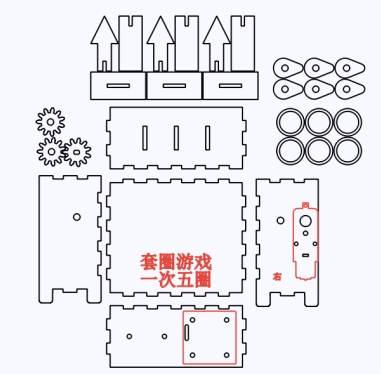
Laser Modeling
With all the preliminary preparations complete, let’s learn together how to create the model for the ring toss game device in the LaserMaker software.
Drawing the Base
After comparing with a sphere, we can use a cubic box as the base because it is not only sturdy but also better suited to accommodate and support structural components compared to a sphere. Additionally, to facilitate inspection and manipulation of the game device by the staff on Planet M, we can use an open box instead of a fully enclosed one.
Although in the LaserMaker software, the drawing of a right-angled box only allows for settings without a top or bottom cover, we can achieve the drawing of a base without a rear cover by slightly modifying the placement of the box later.
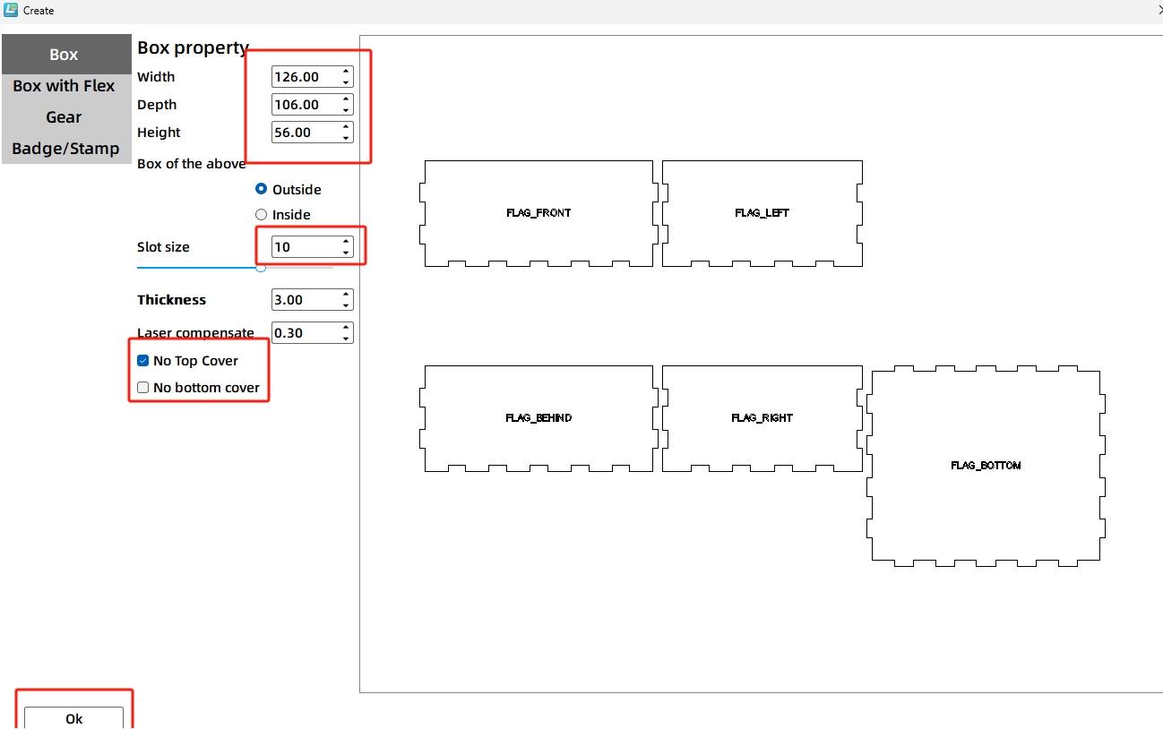
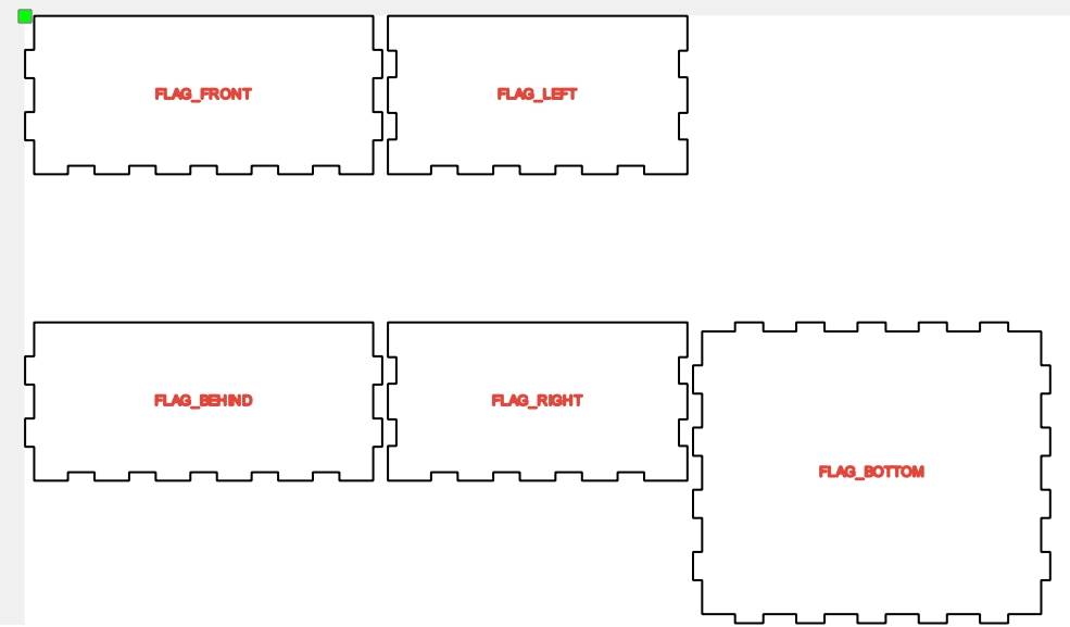
(1) Open the LaserMaker software and click on the “Creation” button in the tool menu. Modify the properties of the right-angled box in the pop-up window, setting the length, width, and height of the box to 126mm, 106mm, and 56mm respectively. Set the groove size to 10mm and check the box for “No Top Cover,” as shown in the following figure. Finally, click the “OK” button, and the imported canvas effect is shown in the following figure.
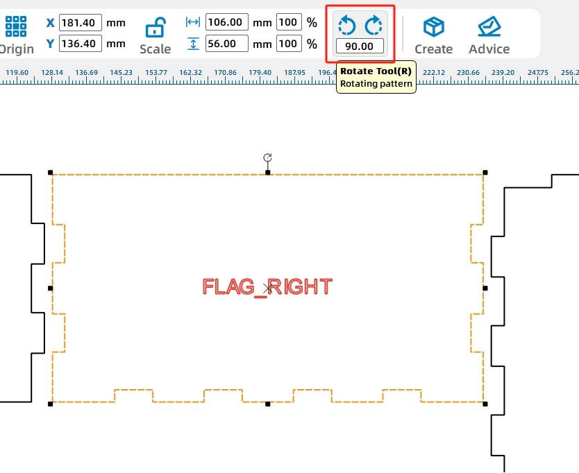
To better design components on each panel, we need to adjust the position of the panels and their corresponding prompts.
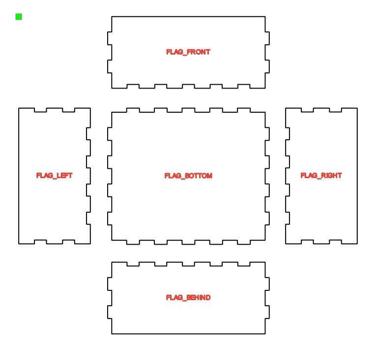
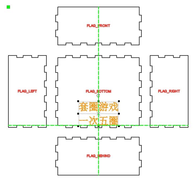
(2) Click on the “Right” panel with the mouse, move the mouse to the rotation marker, enter 90 in the window that appears, click the “Rotate” button, and then click the “Rotate” button on the menu toolbar to adjust the direction. Drag the panel to the left of the “Bottom” panel, as shown in the following figure. Repeat the same operation, rotating and then moving the “Left” panel. Next, use the mouse to drag the “Front” and “Back” panels to the top and bottom of the “Bottom” panel, respectively. Finally, use the mouse to drag each prompt to the corresponding panel and delete any excess prompts, as shown in the following figure.
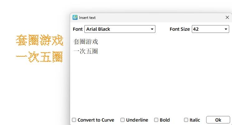
(3) We need to add the game instructions on the box. Click on the ‘Text Tool’ in the drawing tools, enter “Ring Toss Game” and “5 Rings per Turn” in the text box, and click ‘OK’, as shown in the following figure.
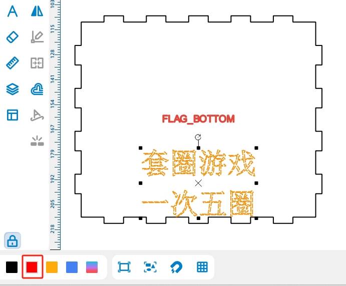
(4) Select the text by clicking on it with the mouse and drag it to the “Front” panel of the box. The completed result is shown in the following figure.
Note: The text “Ring Toss Game, 5 Rings per Turn” is a prompt, and when using a laser cutter, only a trace needs to be scanned. Therefore, the processing technique needs to be modified here, changing the default cutting to scoring.
(5) Click on the text with the mouse, click “General Scoring” in the “Layer Settings,” and change the text content’s processing to “Scoring,” as shown in the following figure.
Since the bottom of the base needs to accommodate the receiver board and battery, and the screws, nuts, and nylon ties used to secure them will penetrate through the bottom panel, this would add height to the originally flat base, making it unstable. Therefore, we need to design support feet for the base.
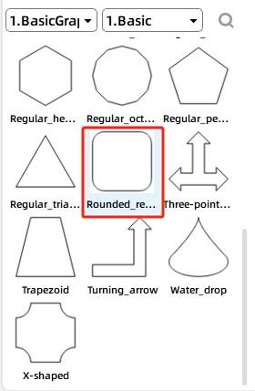
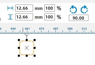
(6) Select the “Rounded Rectangle” from the “1. Basic Shapes” library, as shown in the following figure. Drag the shape to the left side of the bottom of the left panel. Using the measurement tool in the toolbar, we know that the tenon (the leftmost one) at the bottom of the left panel is 12.66mm wide. We will set the width and height of the rectangle to 12.66mm, as shown in the following figure.
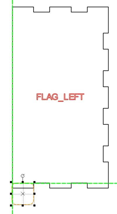
(7) Move the resized rectangle to the bottom of the left panel, with the overlapping height consistent with the tenon height, as shown in the following figure.
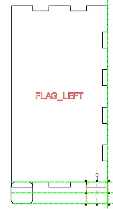
(8) Right-click and use copy and paste to duplicate a rounded rectangle of the same size. Move it to the right side of the panel, and adjust it as shown in the following figure.
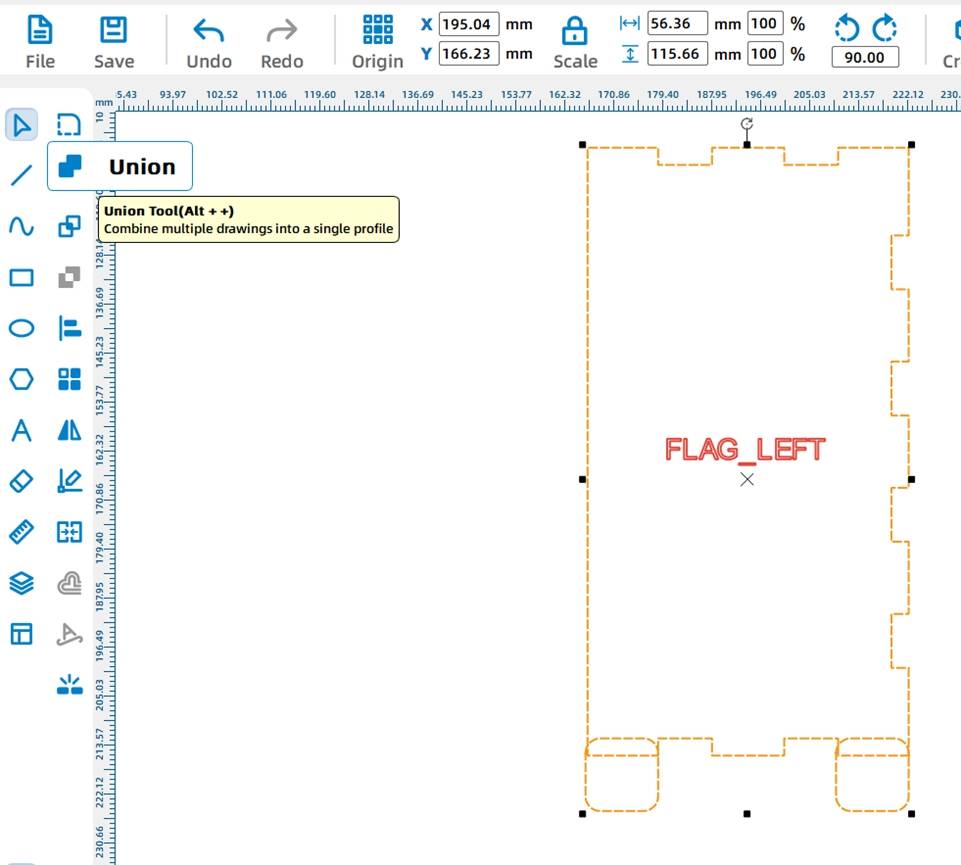
With this, the outlines of the support legs are complete, but they are not yet fully integrated with the box. Here, we need to merge the drawn support legs with the box.
(9) While holding down the Ctrl key on the keyboard, select the left panel and the two rounded rectangles with the mouse, and click the “Union” tool in the drawing tools to integrate the shapes together, as shown in the following figure. The completed integrated effect is shown in the following figure.
(10) Repeat steps (8) and (9) to complete the drawing of the support legs for the right panel. (Observing the left and right panels, we notice that their mortise and tenon structures are identical, so the left panel with support legs can be directly duplicated to replace the right panel without support legs.) The completed design of the support legs on both sides is shown in the following figure.
With the box completed, the next step is to design the fixed holes for the electronic components inside the box. Here, we can utilize the “Grid Tool” in the drawing software to quickly determine the precise positions of each electronic component.
Drawing the Rotating Mechanism
To enable the TT motor to drive the cam rotation more effectively, we can use a 6mm diameter wooden rod instead of the 2mm iron rod that can be directly inserted into the motor shaft. This requires adding a gear system to connect the TT motor and the wooden rod.
The positioning of the TT motor needs to consider not only the location of the round shaft that can drive the gift holder’s rotation, but also the connection with the receiver. Therefore, we should place the motor as close to the edge of the right panel as possible, while maintaining a distance of 7-8mm from the bottom.
(1) Select the “OSROBOT Motor” from the “8. Open Source Robot” library in the graphics library and drag it onto the canvas with the mouse, as shown in the following figure.
(2) Move the mouse to the “Rotate” icon, enter 90 degrees of rotation, and click the “Rotate” button. The completed effect is shown in the following figure.
To enable the inner motor to drive the rotation of the round shaft, a gear set needs to be drawn on the outer side of the base.
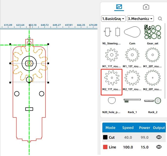
(3) Referring to the size of the TT motor, select the “M2 11t Round Hole” from the “4. Mechanical Parts” library in the graphics library, drag the shape onto the TT motor, and align it with the center of the motor, as shown in the following figure.
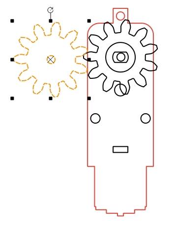
(4) Call the “M2 11t Round Hole” again from the library and align it with the “M2 11t Round Hole” on the TT motor, as shown in the following figure.
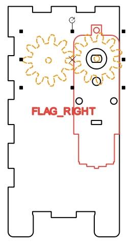
(5) Move the TT motor and gear set onto the “right panel” and align the bottom of the TT motor with the lowest mortise on the left side of the “right panel,” as shown in the following figure.
The TT motor is fixed inside the base and controls the rotation of the round shaft by rotating the gear set outside the base. To allow the wooden round shaft to pass through the base and drive the cam movement, and to reduce friction between the shaft and the base, enhancing the flexibility of shaft rotation, the circular hole on the base can be set slightly larger than the shaft.
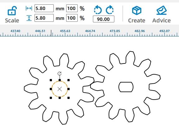
(6) Select the inner circle of the left gear with the mouse, change both the width and height values in the menu bar to 6.2, and press Enter to confirm. As shown in the following figure.
Compared to the circular hole on the panel, the circular hole of the gear that directly connects to the round shaft needs to be slightly smaller than the diameter of the shaft. Having an inner circle slightly smaller than the shaft diameter allows for a more secure fit, ensuring that when the gear rotates, the shaft also rotates.
(7) Select the gear set, right-click, and select Copy, then Paste as shown in the following figure. Select the inner circle of the left gear and set the width and height of the circle to 5.8mm, as illustrated in the following figure.
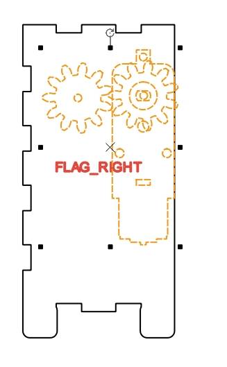
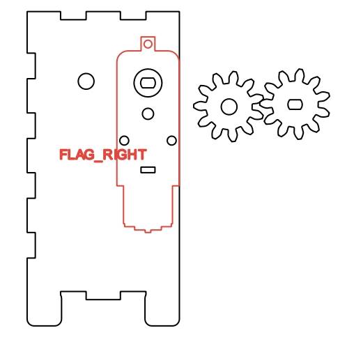
(8) Delete the unnecessary gear components on the right panel, as shown in the following figure.
After the shaft hole on the right panel is completed, to align the shaft hole on the left panel with that on the right panel, you can choose to replicate the right panel to quickly obtain a panel with a round wooden rod hole.
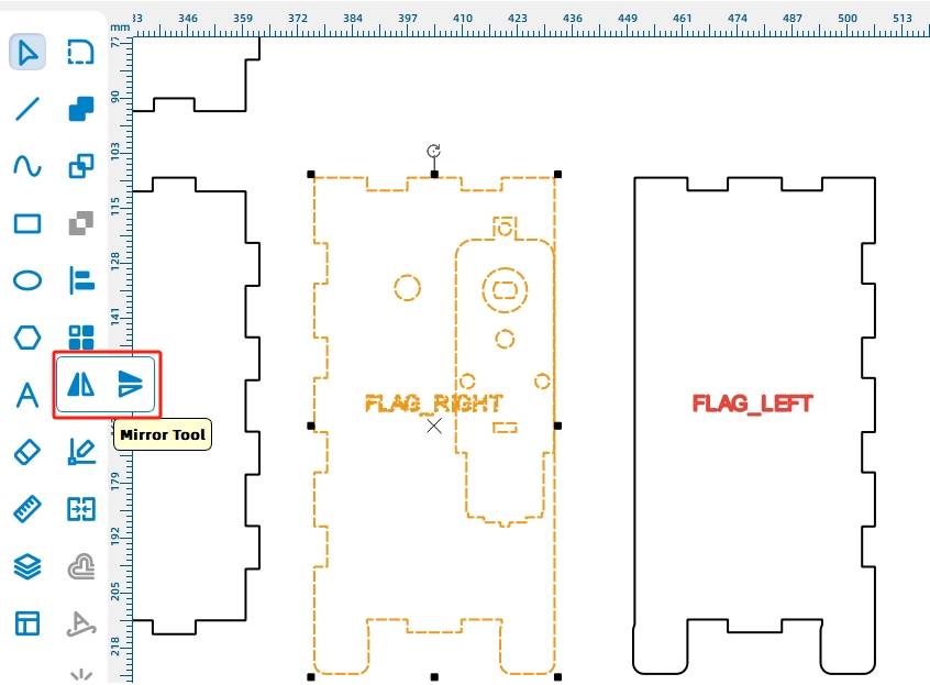
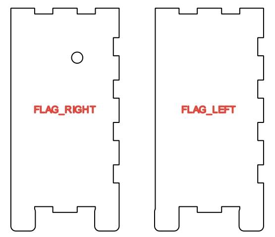
(9) Select the right panel, right-click to copy, and then paste. Move the copied panel next to the left panel, as shown in the following figure. Remove extra holes and prompts, leaving only one round shaft hole, as shown in the following figure.
(10) To prevent the round shaft from detaching from the left panel during rotation, a gear needs to be added to the left side of the shaft for fixation. Select the gear with the round shaft hole, right-click, and choose “Copy” and “Paste” to obtain the left panel.
Creating the Gift Rack
Considering the limited width of the base and the placement of the motor that drives the shaft inside the base, designers have modified the gift rack’s base to a vertical arrangement, allowing for three identical gift racks. The gift rack consists of three parts: the base that comes into contact with the cam, the arrowhead top for the ring, and the connecting component between the two. As shown in the following figure.
Let’s start by drawing the base of the gift rack. The base and connecting component will be assembled together in a mortise-and-tenon joint, so we need to create a mortise in the base.
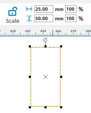
(1) Click on the “Rectangle Tool” in the drawing toolbox and draw a rectangle with a width of 25mm and a height of 50mm on the canvas, as shown in the following figure.
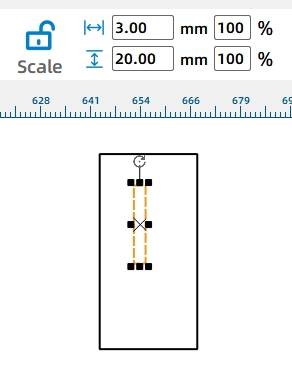
(2) Repeat step (1) to draw a rectangle with a width of 3mm and a height of 20mm inside the larger rectangle, as shown in the following figure.
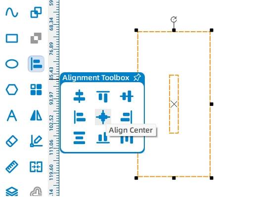
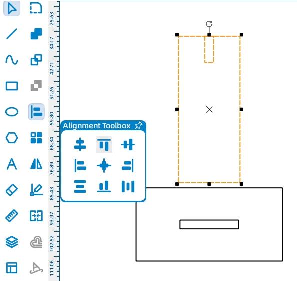
(3) Click on the “Selection Tool” in the drawing toolbar, click and drag to select both rectangles. Then, click “Horizontal Center Alignment” and “Vertical Center Alignment” in the “Alignment Toolbox” in the drawing toolbar, as shown in the following figure. The aligned result is shown in the following figure.
After completing the drawing of the gift rack’s base, the next step is to draw the connecting part. The connecting part can be directly inserted into the mortise of the base to form a mortise-and-tenon joint. To make the gift rack fit tighter, the tenon’s width can be increased from 20mm to 21mm.
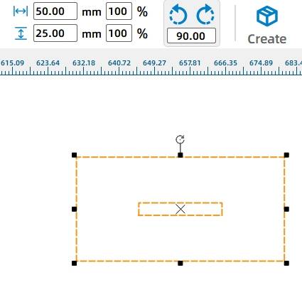
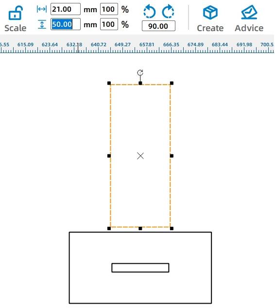
(4) Repeat step (1) to draw a rectangle with a width of 21mm and a height of 50mm, as shown in the following figure.
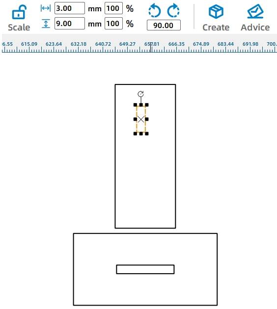
(5) Next, we need to create a mortise on the connection component so that the arrowhead of the gift rack can be inserted vertically later. Repeat step (1) and draw a rectangle with a width of 3mm and a height of 9mm, as shown in the following figure.
(6) Select both rectangles and click “Horizontal Center Alignment” and “Top Alignment” in the “Alignment Toolbox” consecutively. The aligned result is shown in the following figure.
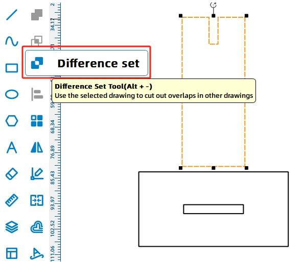
(7) Click to select the smaller rectangle, then click “Difference” in the drawing toolbar to complete the mortise drawing as shown in the following figure.
With the base of the gift rack complete, we can now proceed to making the top surface of the gift rack, which is where the game rings will be hung.
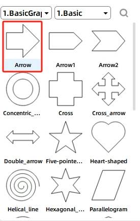
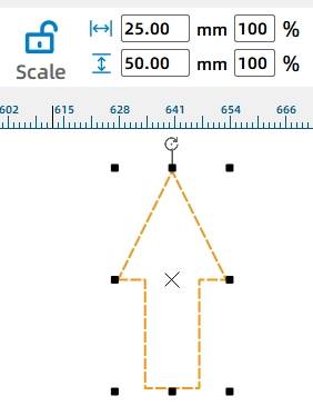
(8) Use an arrow as the structure for the ring-hanging part. Select the “Arrow” from the “1. Basic Shapes” library in the gallery and drag the shape onto the canvas, as shown in the following figure.
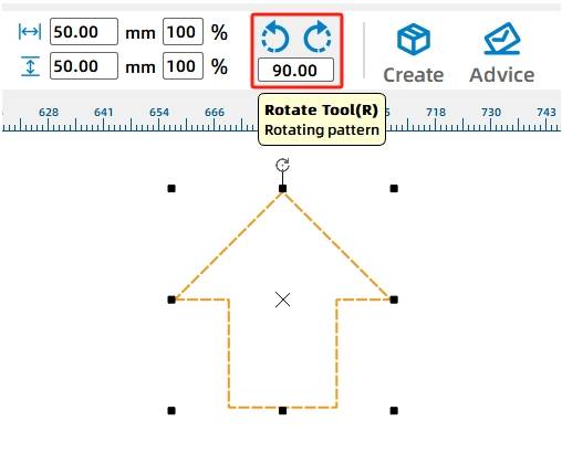
(9) Move the mouse cursor to the rotation button, enter 90, and click to rotate the arrow upward, as shown in the following figure. Meanwhile, adjust the “Width” in the menu bar, set it to 25mm, and press Enter to confirm, as shown in the following figure.
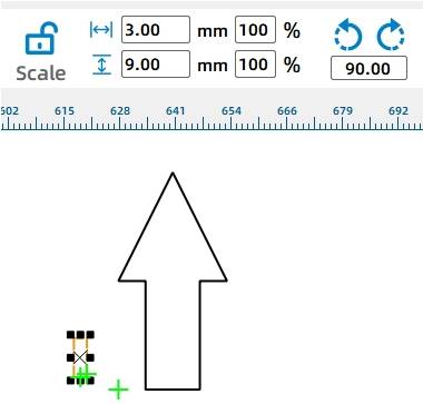
Next, we need to add a mortise to the arrow so that it can be tightly inserted into the previously designed connector.
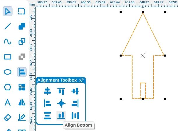
(10) Click on the “Rectangle Tool” and draw a rectangle with dimensions of 3mm x 9mm, as shown in Figure 5-39. Select the rectangle and the arrow using the mouse, and click “Horizontal Center Alignment” and “Bottom Alignment” in the “Alignment Toolbox” consecutively, as shown in the following figure. The final aligned result is shown in the following figure.
(11) Select the small rectangle and click on the “Difference” tool in the drawing toolbar, as shown in the following figure.
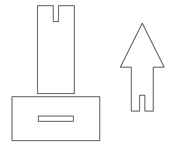
At this point, a complete gift rack is finished, as shown in the following figure. Depending on the width of the gift rack and base, it is necessary to create two more identical gift racks.
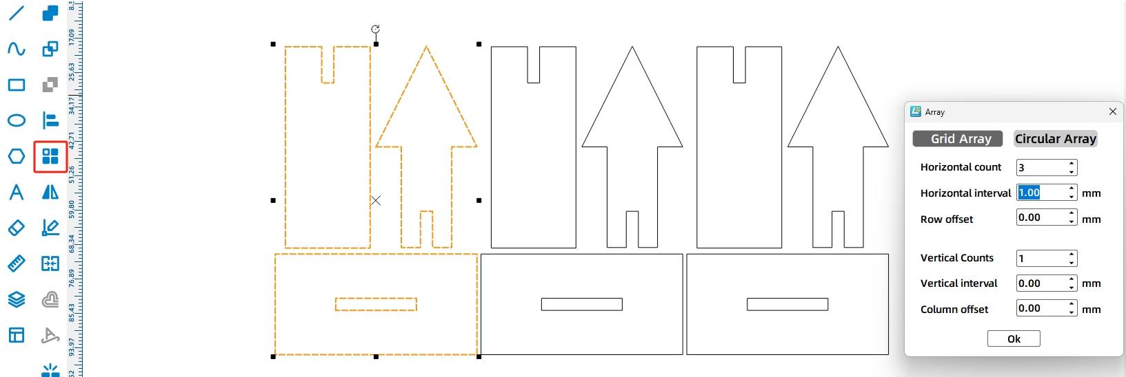
(13) Use the mouse to select all the gift racks and click on the “Rectangle Array” tool in the “Tools Menu Bar”. Set the corresponding parameters to draw three identical gift racks, as shown in the following figure.
After completing the circular holes on the panel, we proceed to design the crucial part – the cam. Leveraging its unique characteristics, the cam can achieve linear reciprocating motion of the gift racks through its own circular motion.
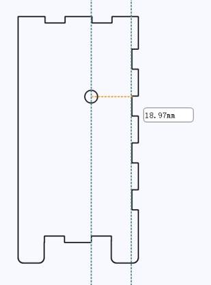
(14) Select the “Cam” from the “4. Mechanical Parts” library and drag it onto the canvas, as shown in the following figure. Add auxiliary lines at the center of the circular hole and the bottom of the mortise on the panel. Through measurement estimation, we find the distance between them is 18.97mm, as illustrated in the following figure.
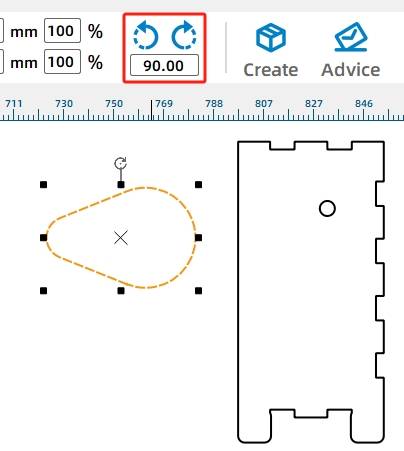
(15) To ensure that the cam does not touch the base when rotating, we need to adjust its size. Click on the “Uniform Scaling” tool in the “Menu Toolbar” to lock the aspect ratio of the shape. Set the percentage value to 45 and press Enter to confirm. This will uniformly scale down the original drawing, as shown in the following figure.
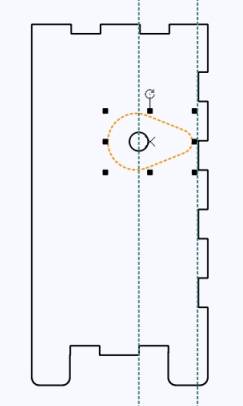
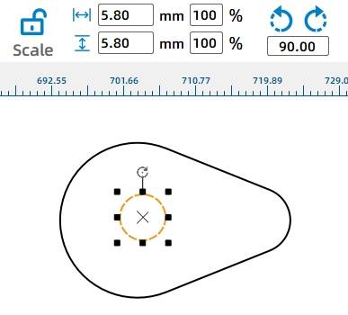
(16) After completing the contour design of the cam, we need to create an axle hole in the graphic. The axle hole for the cam should fit a 6mm wooden rod, so we can use the “Ellipse Tool” in the “Drawing Tools” to draw a perfect circle with a diameter of 5.8mm. Drag the circle to the center of the cam using the mouse. For irregular shapes like the cam, you can set the circle’s position based on the object’s origin point. Refer to the object’s origin position in the image of the cam to modify the corresponding coordinates of the circle, as shown in the following figure.
To improve the contact between the gift rack’s base, stack two cams to increase their thickness and contact area.
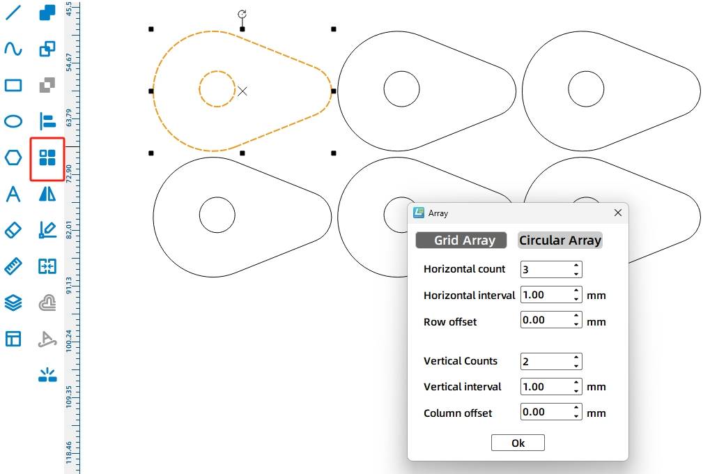
(17) Select the cam with the circular hole and click “Rectangle Array” in the tool menu to create six cams spaced 1mm apart. See the following figure for array parameter settings.
Let’s finish drawing the hole positions on the top and bottom panels.
Next, to enable the gift rack to move smoothly up and down through the base, we need to draw a rectangular hole on the top surface of the base.
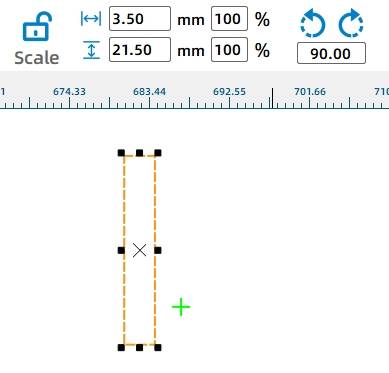
(18) Click the “Rectangle Tool” in the drawing menu bar and draw a rectangle with a width of 3.5mm and a height of 21.5mm, as shown in the following figure.
After designing the hole positions for a gift stand, we can duplicate two identically sized hole positions using the rectangular array tool through calculation.
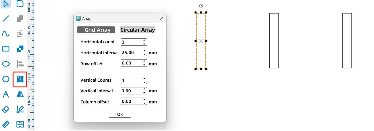
(19) Click the “Rectangular Array” option on the toolbar menu. Set the specific parameters as shown in the figure below to complete the drawing of three rectangles spaced 25mm apart, as illustrated in the following figure.
Note: The “Horizontal Spacing” is calculated based on the width of the top panel of the base box and the dimensions of the built-in TT motor.
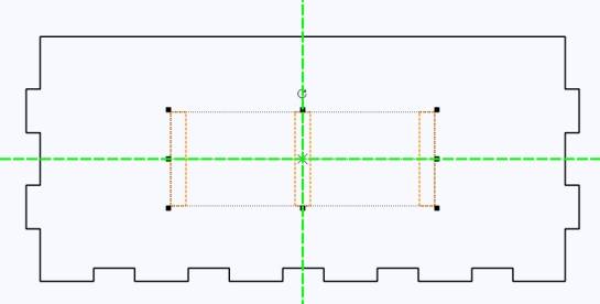
(20) While holding the Ctrl key, click on each of the three rectangles with the mouse and drag the selected shapes to the center of the “top” panel of the box, as shown in the following figure.
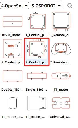
(21) Click on the “Grid Tool” and select the “OSROBOT Receiver Board” from the “9. Open Source Robot” library in the gallery. Then drag and drop the graphic onto the base panel, as shown in the following figure.
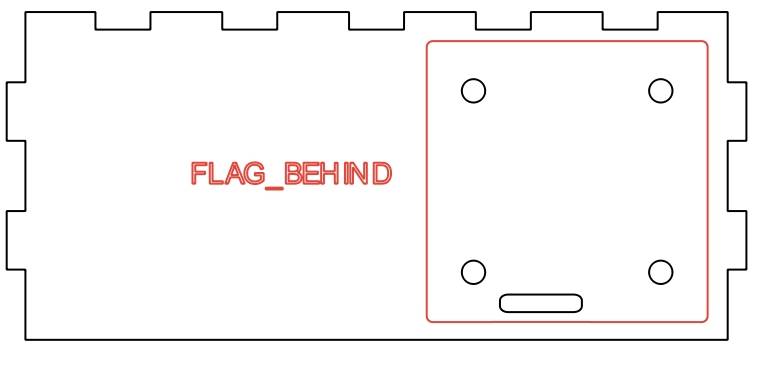
(22) In the design of the ring toss game device, we need to hide the motor, battery, and receiver board inside the base. Therefore, we can directly delete the unnecessary wire holes on the receiver board, and the completed effect is shown in the following figure.
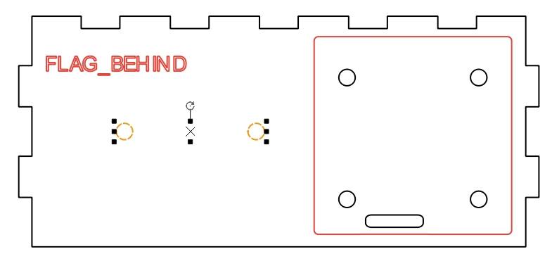
After determining the hole positions for the receiver board, we can proceed to add the mounting holes for the 18650 battery. We can directly duplicate the screw holes on the receiver board to use as the threading holes for the nylon cable ties.
(23) Hold down the mouse button to select the two vertical circular holes on the receiver. Right-click and select “Copy” and then “Paste” consecutively. Move the duplicated holes to the other side of the base panel, as shown in the following figure.
Drawing the Game Rings
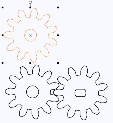
After completing the core part of the ring toss game, designers also need to draw the last component, the essential game rings. Drawing the game rings is simple; they are composed of two concentric circles with different diameters.
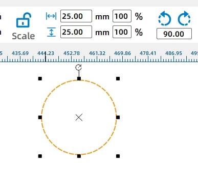
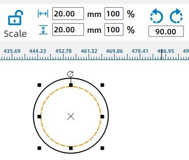
(1) Click on the “Ellipse Tool” in the drawing toolbox and hold down the Ctrl key to draw circles with diameters of 25mm and 20mm, as shown in the following figure.
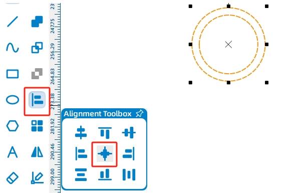
(2) Select both circles, click “Align Horizontally” and “Align Vertically” in the Alignment Toolbox to center the two circles. The alignment effect is shown in the following figure.
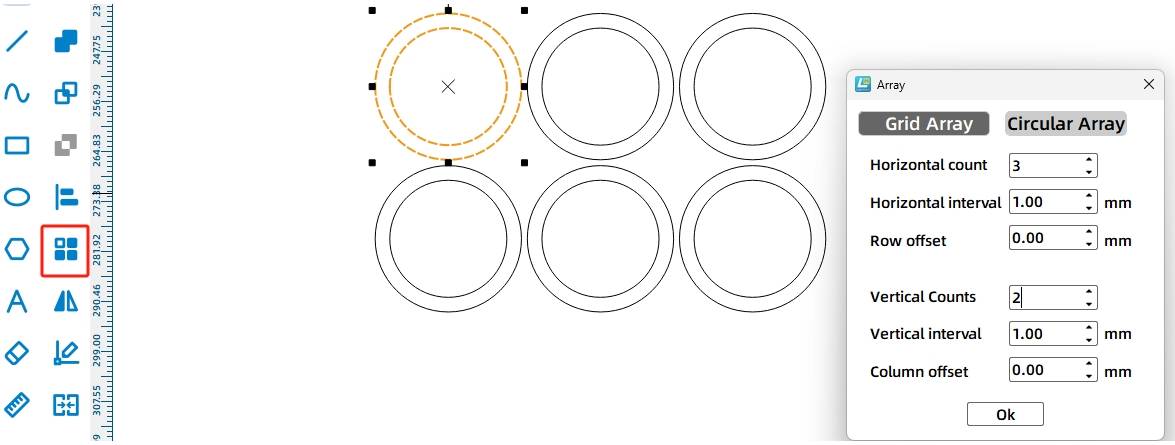
(3) After making a game ring, replicate it using the rectangular array function. Select the two circles with the mouse, click “Rectangular Array” in the tool menu, and draw 6 rings with a spacing of 1mm, as shown in the following figure.
After verification, press Ctrl, select all annotations or auxiliary lines, right-click to delete, and quickly save the file to the specified folder, as shown in the following figure.
Laser Processing
After completing the design and drawing of the drawing, you can use a laser cutting machine to cut out the design. It is best to check and confirm the processing technology settings again in the software, click “Simulate Fabrication” and click the “Start” button in the pop-up window to further confirm the process sequence such as tracing and cutting. Then we can import the file into the laser cutting machine to complete the cutting of the work. The actual cutting diagram of the hoop game is shown in
Model Assembly
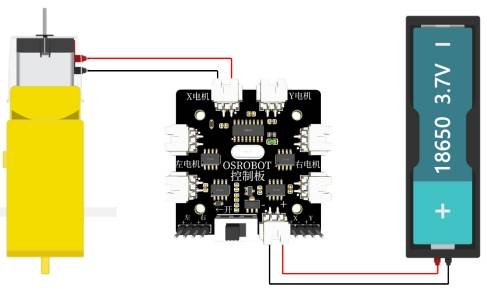
Circuit Wiring
After the assembly of the hoop game model is complete, we connect the circuit according to the wiring diagram shown in the following figure. Since the speed of the hoop game should not be too fast, here we use a single 18650 battery and a motor with a gear ratio of 1:220.
With the parts of the hoop game cut and the circuit wiring of the equipment clear, we can start assembling.
Structural Assembly
Secure the TT motor, 1 18650 battery box, and 2.4G receiver to their respective positions using screws and nuts. Assemble the base, gift holder, and rotating mechanism. The specific steps are as follows:
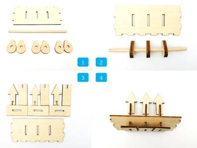
Step 1: Find the cam, wooden stick, and the upper panel of the base.
Step 2: Referring to the spacing of the holes on the upper panel, install the cam on the wooden stick and adjust the distance between the cams according to the hole spacing on the upper panel.
Step 3: Find the three bottom supports of the gift holder, the arrow, and the middle vertical plate.
Step 5: Find the left and right panels of the base, gear set, rotating shaft, and related accessories.
Step 6: First, secure the motor to the right panel, then pass the rotating shaft through the left and right panels, fixing both ends with round-hole gears. Finally, install the gear with a TT hole on the motor to engage with the gear on the rotating shaft.
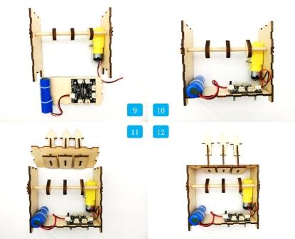
Step 7: Find the bottom panel of the base, 18650 battery, receiver, nylon cable ties, and screws and nuts.
Step 8: Secure the receiver and 18650 battery to the base using screws, nuts, and nylon cable ties.
Step 9: Find the bottom panel of the base and the rotating mechanism.
Step 10: Install the rotating mechanism on the bottom panel.
Step 11: Find the upper panel of the base.
Step 12: Install the upper panel with the gift holder onto the base.
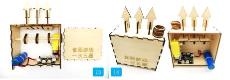
Step 13: Find the front panel with the game introduction.
Step 14: Install the front panel while placing the game rings on the gift holder.
Summary
During the process of making the hoop game, we learned how to use gear transmission and cam mechanisms to convert circular motion into linear reciprocating motion, adding fun to the traditional project and attracting the attention of many M-planet players. The Creator Factory has once again successfully completed its task. It is said that the next task is a water project. Let’s go and take a look!
Thought Expansion
For this project, the gift stand directly uses wooden arrows, and players exchange gifts based on the number of hoops they land on. Could we design a gift stand with textual prompts to attract more game participants in a more direct way? Or could we convert the gift stand into a box that holds gifts? Do you have any better ideas?
Additionally, where else in daily life do we see the application of gear transmission and cam mechanisms? What other interesting projects could we create using cam mechanisms? Let’s have a brainstorming session with friends around us.


.jpg)

.png "laser cutter Globle")


