After careful design by our engineers, the collection vehicle has successfully achieved the task of harvesting energy stones. Now, our team is hurriedly working on a dump truck specifically designed for loading and unloading these stones. The primary function of this dump truck is to transport energy stones from the mining site to the warehouse in the arena. Let’s eagerly anticipate the grand debut of this exclusive dump truck for Planet M.
Determining the Design Scheme
Analysis of the Product
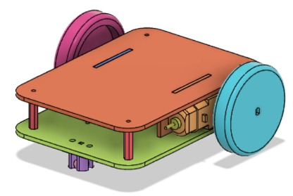
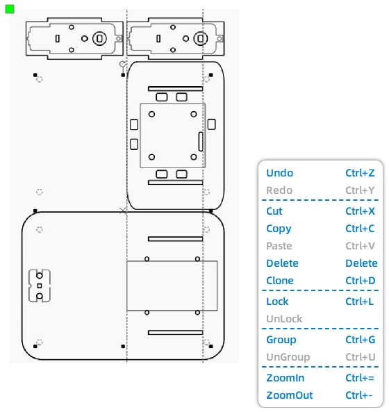
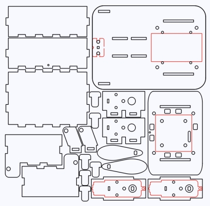
In real-life applications, dump trucks commonly utilize hydraulic systems to control the tilting mechanism for loading, unloading, and resetting. However, for this project, we will employ the remote control package from the OSROBTO open-source robot to replicate the functionality of a hydraulic system. To accomplish this, we will need to modify the previously designed universal chassis, as shown in the following figure, by adding an additional dump body.
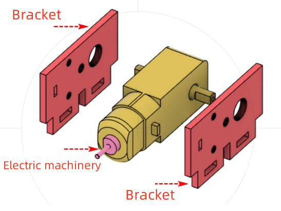
We can adjust the position of the motors (driving motors) on the vehicle’s base plate that controls tire rotation, relocate the OSROBOT receiver to the vehicle’s roof, and position the battery pack, the motor that powers the dump body rotation (dump motor), and the mechanism that controls the dump body rotation on the bottom panel of the vehicle body, as shown in the following figure.
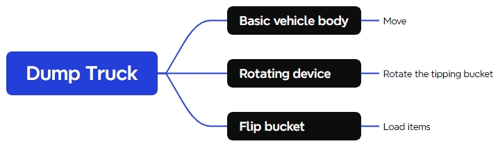
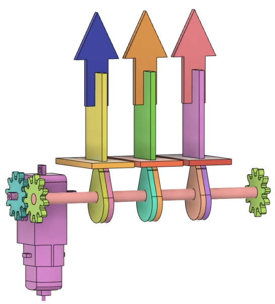
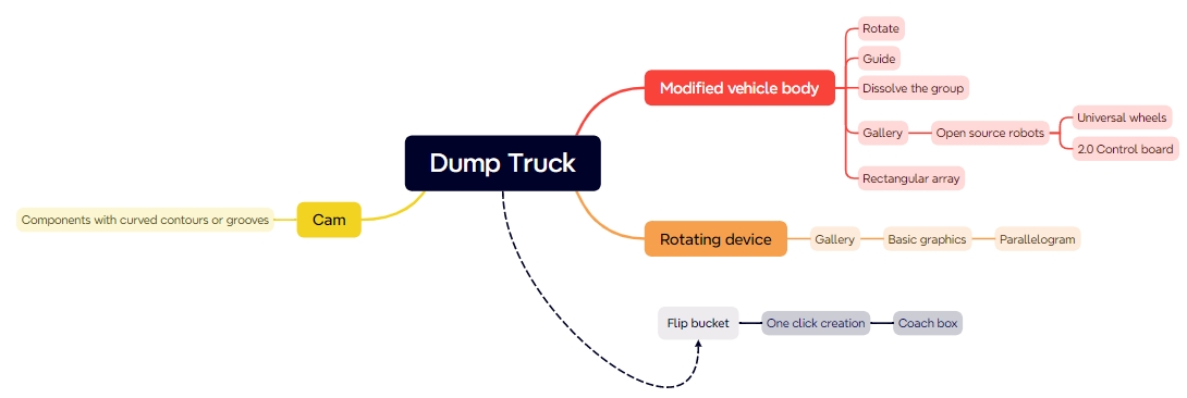
Based on this analysis, we can quickly identify the main components of the dump truck apparatus: the vehicle body, the tilting mechanism for the base, and the dump body itself.
Equipment List
Using the dump truck design mind map, we can identify the necessary components and complete the equipment list at the makerspace. Here is a summary of the required items as shown in the following Table.
No.
Item Name
Quantity
1
Base Vehicle (Detailed Reference in Advanced Section 1)
1
2
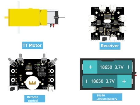
2.4G Receiver
1
3
Basswood Plywood (40cm x 60cm x 3mm)
2
4
Dual-Axis TT Motor (1:48 Gear Ratio)
1
5
Round Wooden Rod
1
6
Screws and Nuts
Several
7
Rubber Bands and Nylon Cable Ties
Several
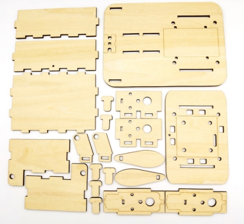
Structural Design
Creating a Parts List
After selecting the appropriate components for the dump truck, we need to further refine the list of exterior structural parts, as shown in the following Table.
Part No.
Part Name
Quantity
Function
1
Vehicle Body
1
To house motors, batteries, and receiver
2
Pivot Base
2
To enable rotation of the dump bed
3
Dump Bed
1
To carry items
Laser Modeling
The preliminary preparations have been completed, and now we can start to improve the design drawing of the basic car body using LaserMaker software.
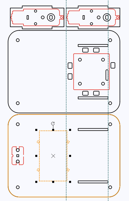
Modify the Car Body
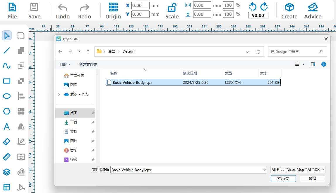
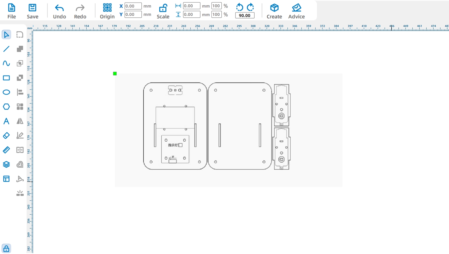
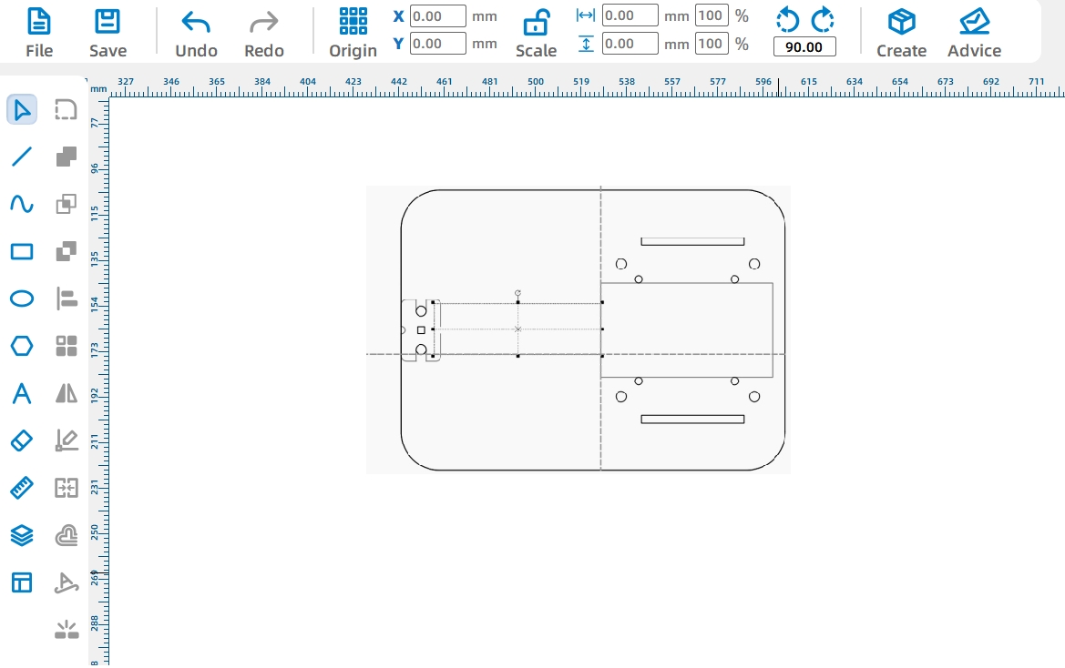
(1) Double-click to open the LaserMaker software, click “Open” on the toolbar, find the “CarBody.lcp” file in the pop-up window, click the “Open” button, as shown in the following figure, and the file import effect is shown in the following figure.
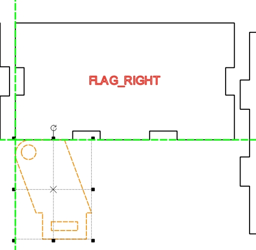
To facilitate the drawing of newly added components, we can first adjust the placement of the base car body design.
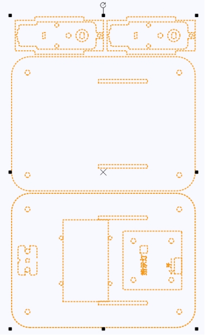
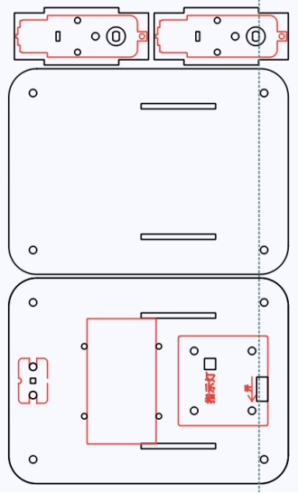
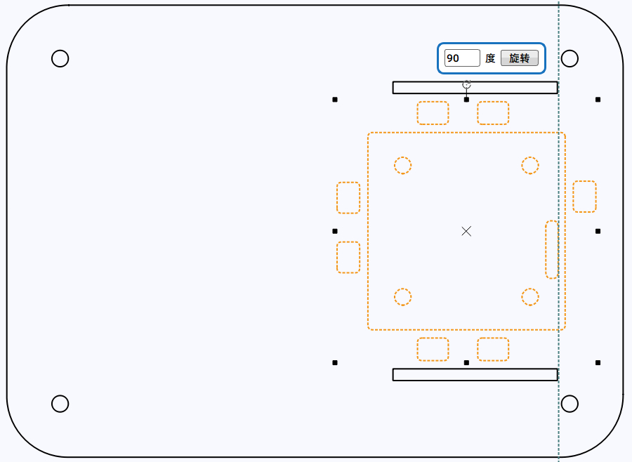
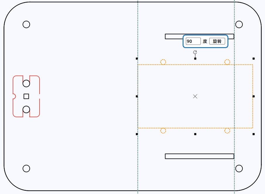
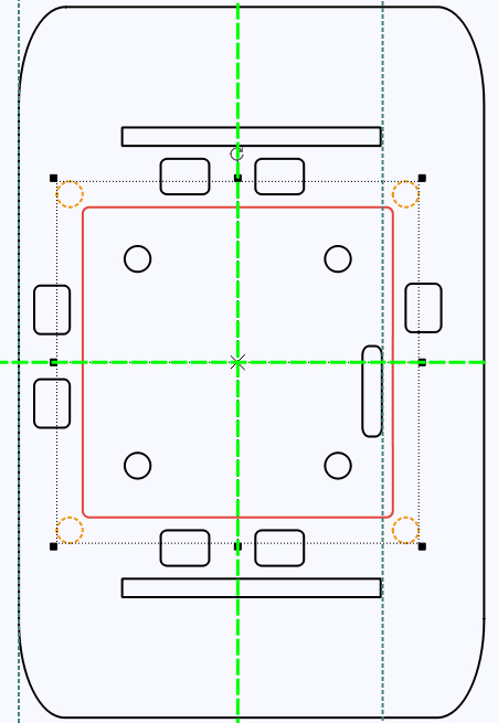
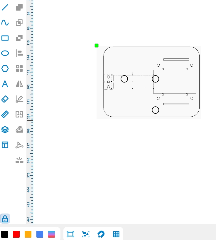
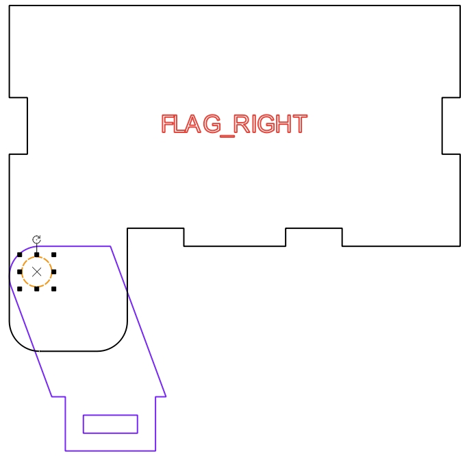
(2) Use the “Ctrl+A” key combination on the keyboard to select all the car body drawings, then click the “Rotate” button on the toolbar to rotate the car body 90° and place it horizontally, as shown in the following figure.
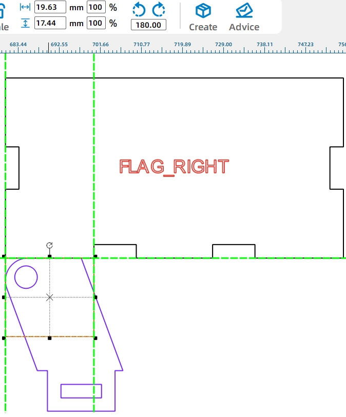
Since the added tilting motor needs to be placed on the bottom panel, we first adjust the installation position of the driving motor to make room for the tilting motor (the above figure).
(3) To adjust the position, we can use the auxiliary line tool in LaserMaker software. Specifically, move the mouse cursor to the left ruler bar, click and hold the mouse button, and move the auxiliary line to the right side of the motor’s fixed wooden board, aligning it with the right side of the tenon on the fixed wooden board. As shown in the following figure.
(4) Next, we’ll move the hole positions for the motor mounting plate. Press and hold the Ctrl key on the keyboard, then use the mouse to sequentially select the hole positions (i.e., mortises) on the motor mounting plate in the car body. Move them to the auxiliary line and align their right ends with the auxiliary line, as shown in Figure 11-10. The completed effect is shown in the following figure.
Next, for ease of manipulation, we can place the control board on the top panel of the car body. After comparison, we found that it would be more convenient to directly delete the original control board and re-use an external control board with wiring holes from the library.
(6) Click to select the controller on the bottom panel and right-click to choose “Delete,” as shown in the following figure.
(7) Click on “2.0 Control Board (External)” in the “9. Open-Source Robot Hardware” library, drag the graphic to the top panel of the car body, and align it centrally with the motor mounting plate holes, as shown in Figure 11-13. Simultaneously, click the “Rotate” button in the menu toolbar to adjust the power port of the control board to the rear of the car body, as shown in the following figure.
After adjusting the position of the control board, we can start moving the battery component.
(8) Select the battery component, then move the mouse to the “Rotate” button and change it to a horizontal position. Subsequently, drag it to the bottom panel of the car body and align it centrally with the motor mounting plate holes, as shown in the following figure.
Next, we need to prepare to shorten the top panel of the car body to leave enough space for the tilting motor.
(9) Select the top panel, move the mouse to the black control point in the middle of the left side, and when the mouse icon changes to a double-headed arrow, hold the mouse button and move it horizontally to the right, reducing the width of the top panel of the car body to the width of the fixed motor panel. As shown in the following figure.
Of course, with the reduction of the top panel, the position of the nylon pillar holes used to fix the two panels of the car body also needs to be adjusted. In addition, the adjustment will cause the original nylon pillar holes to be on the driving motor, making it impossible to install the nylon pillars during later assembly. Therefore, we also need to redraw the nylon pillar holes with the top control board as a reference.
(10) Hold down the Ctrl key, click on the nylon pillar holes on the top and bottom panels in sequence, right-click after selecting, and click “Delete” in the pop-up window, as shown in the following figure.
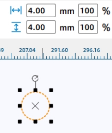
(11) Click the “Ellipse Tool” in the left drawing toolbox, unlock the aspect ratio lock by clicking the aspect ratio button in the menu bar, and then draw a perfect circle with a diameter of 4mm, as shown in the following figure.
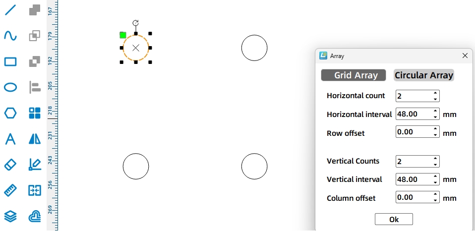
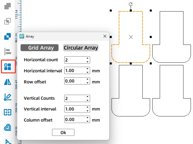
After completing the drawing of a single hole position, we can use the control board as a reference and replicate 4 nylon pillar hole positions using a rectangular array method (Note: The length and width of the control board are both 48mm).
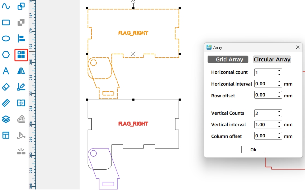
(12) Click “Rectangular Array” on the tool menu bar, set “Number of Rows” and “Number of Columns” to 2 in the pop-up window, set “Horizontal Spacing” and “Vertical Spacing” to 48mm, and click “OK”, as shown in the following figure.
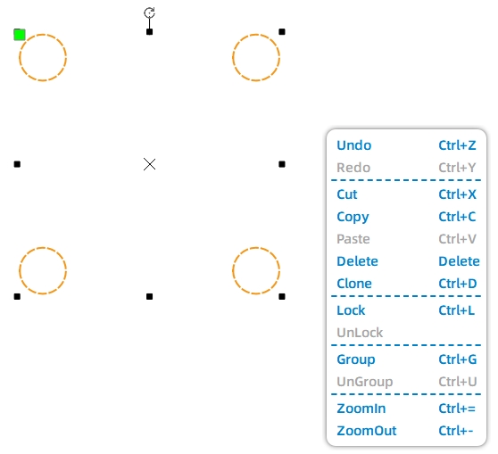
To facilitate the copying and moving of the hole positions to the top and bottom plates, we will first group the nylon pillar hole positions.
(13) Right-click and select “Group” as shown in Figure 11-20. Then, move the grouped nylon pillar hole positions to the top plate and align them with the center of the control board, as shown in the following figure.
Considering that the bottom panel has no control board as a reference and to ensure consistency of the hole positions between the two panels, we will use the common mortise hole positions (i.e., tenons) on both the top and bottom panels as a reference.
(14) Holding down the Ctrl key, click to select the nylon pillar hole positions and the mortise hole positions on the top panel sequentially. Then, use the “Ctrl+C” and “Ctrl+V” key combinations to quickly copy and paste them, as shown in the following figure.
(15) Move the copied graphics to the bottom plate and align them with the fixed hole positions on the bottom plate. Then, select and delete the copied mortise hole positions with the mouse, leaving only the nylon pillar hole positions, as shown in the following figure.
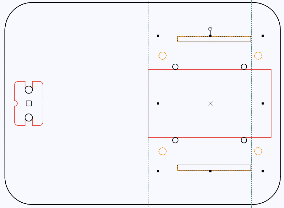
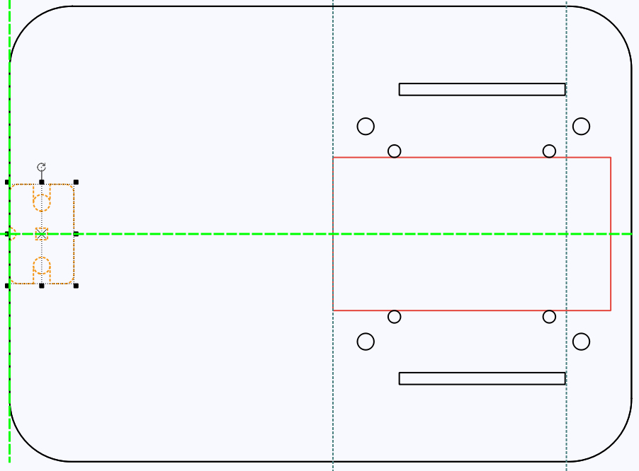
Additionally, to prevent the fixed screws of the caster wheels from interfering with the installation of the dump motor, the position of the caster wheels needs to be moved to the frontmost end of the bottom panel of the car body.
(16) Click and drag the box surrounding the caster wheel graphics to the center point of the left edge of the bottom panel, as shown in the following figure.
After making adjustments to each part of the basic car body, we have completed the transformation of the basic car body. Of course, besides this method, we can also directly utilize the known parameters of the basic car body to redraw a new dump truck body.
Next, let’s follow the designer to draw the rotating mechanism that enables the dump truck to load and unload.
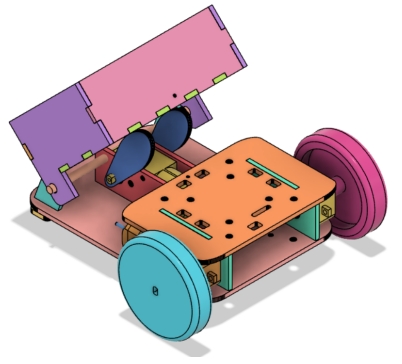
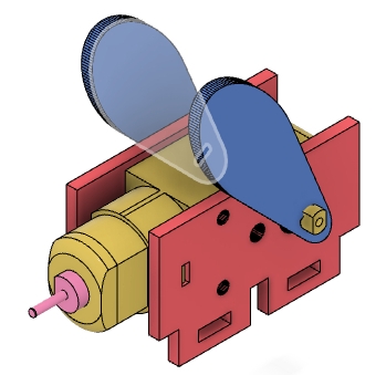
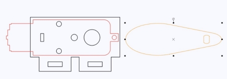
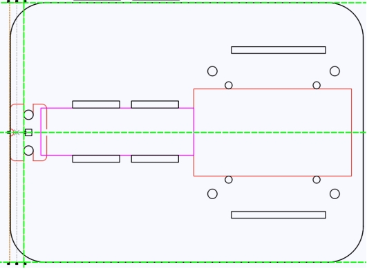
The rotating mechanism of the dump truck mainly includes a force-generating component that drives the cam to rotate and a rotating shaft component that drives the dump body to flip. Designers have decided to use the cam as the core component of the force-generating assembly. As shown in the following figure, to achieve the loading and unloading actions of the hopper, it is necessary for the hopper to flip flexibly. In the previous game of ring toss, the designer borrowed the cam to change the trajectory of the gift shelf, and it worked well. As shown in the following figure, we can also utilize the elliptical curve of the cam to achieve the up and down flipping of the dump body.
Designing the Rotating Mechanism
Designers plan to complete the force-generating component of the rotating mechanism first, which consists of a dump truck motor and a cam. Therefore, to smoothly fix the dump truck motor to the car body, we can first measure the size of the motor and draw a contour outline of the motor horizontally placed on the car body to assist in determining the hole positions for the motor fixing board.
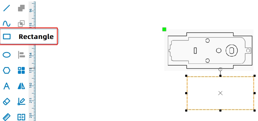
(1) Click the “Rectangle Tool” in the drawing toolbar, draw a rectangle with a width of 65mm and a height of 20mm in the canvas, and move this graphic to the left of the battery component, centered vertically, as shown in the following figure.
After adjusting the position, you also need to modify the color of the graphic to increase its visibility and convenience for later drawing.
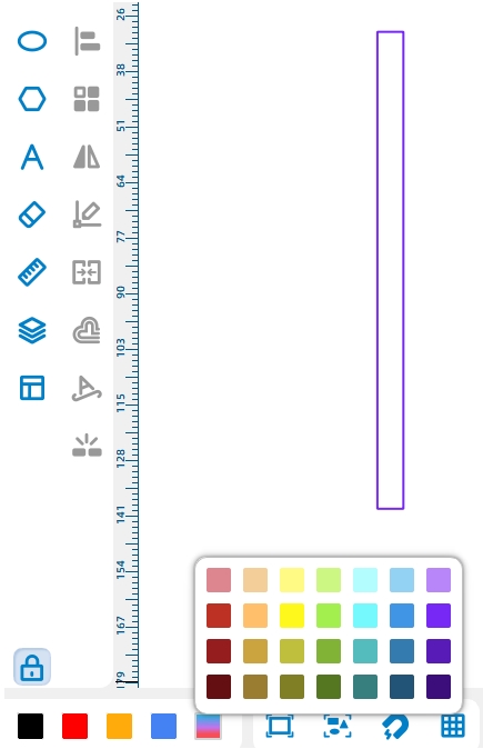
(2) Click “More” in the “Layer Settings” at the bottom and select “Purple,” as shown in the following figure.
With the motor cross-section reference in place, let’s draw the mounting panel for the dump truck motor, as shown in the following figure. At the same time, to maintain the overall aesthetics of the car body, the height of the dump truck motor should be kept consistent with the height of the driving motor.
(3) Click the “Rectangle Tool” in the drawing toolbar and use the driving motor as a reference to draw a rectangle with a width of 56mm and a height of 25mm, as shown in the following figure.
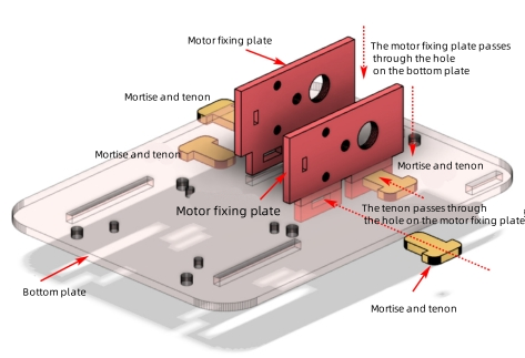
From the 3D view, it can be seen that there is no top plate above the hopper motor. To ensure that the mounting panel can be securely installed on the bottom plate, designers have decided to adopt a “dowel” connection method, where the mounting panel passes through the holes on the bottom panel and is then fixed with tenons, as shown in the following figure.
With the connection method clarified, let’s start drawing the tenon and mortise for the mounting panel.
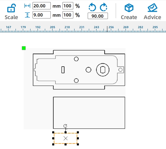
(4) Click the “Rectangle Tool” with your mouse and draw a tenon with a width of 20mm and a height of 9mm in the canvas, as shown in the following figure. Then draw a mortise with a width of 9mm and a height of 3mm, as shown in the following figure.
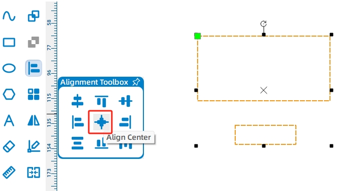
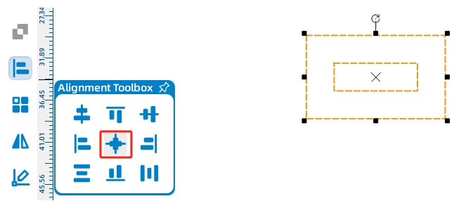
(5) Select the tenon and mortise with the mouse, click the “Align” tool in the drawing toolbox, then click “Horizontally Center” and “Vertically Center” successively. The merged effect is shown in the following figure.
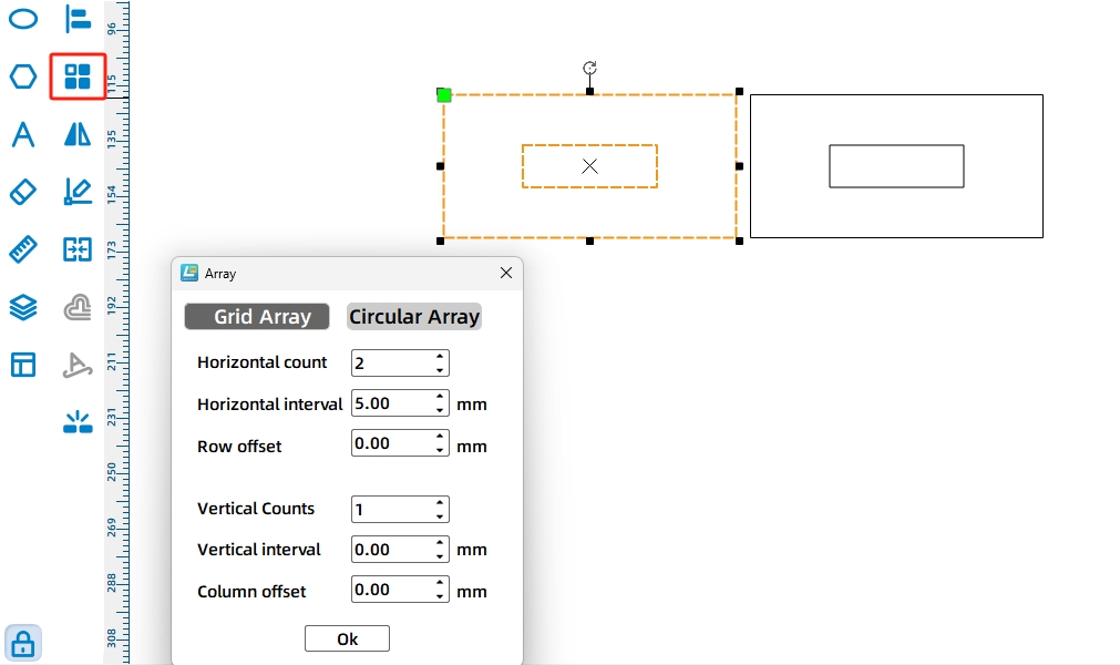
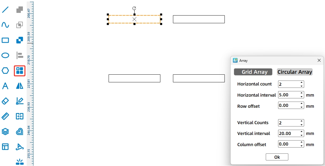
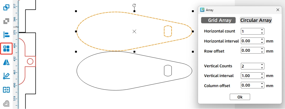
(6) Click “Rectangular Array” on the “Tools Menu Bar”. In the pop-up window, change “Number of Columns” to 2 and “Horizontal Spacing” to 5, then click OK, as shown in Figure 11-35. Place the two generated tenons at the bottom of the mounting panel and keep them horizontally centered, as shown in the following figure.
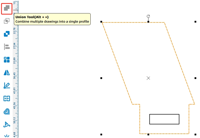
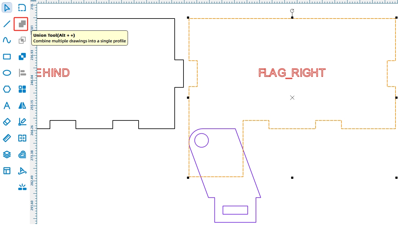
After adjusting the graphics, they need to be combined into one unit.
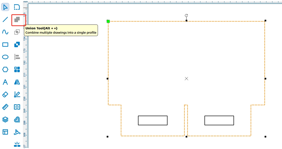
(7) Holding the Ctrl key, click and select the mounting panel and tenons in sequence. Then click “Union” in the Drawing Tools, and the combined result is shown in the following figure.
After determining the outline of the motor mounting panel, let’s proceed to draw the motor shaft holes for the mounting panel.
(8) Referring to the position of the motor in the existing mounting panel, locate the “TT Motor” from the library “9.0 Open-Source Robot Hardware”, click to select it, and drag it into the mounting panel for the third motor, as shown in the following figure.
To ensure the stability and reliability of the dump motor installed in the baseplate, we can place fixed plates on both sides of the hopper motor.
(9) Select the fixed plate of the dump motor with the mouse, click “Rectangular Array” in the tool menu bar, set the corresponding parameters, click “OK”, as shown in the following figure.
(10) To facilitate the drawing of the hole positions for the vehicle’s body mounting plate later, it needs to be moved above the base plate and aligned to the right with the motor cross-section, as shown in the following figure.
With the completion of the design of the dump motor mounting plate, we will now proceed to design the mortise-tenon pin that will fit with the mounting plate. Here, we can use the method of combining two rectangles to draw the T-shaped mortise-tenon.
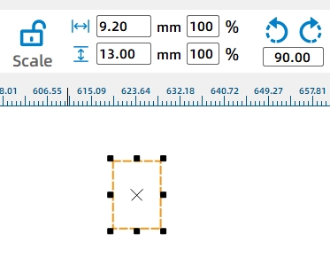
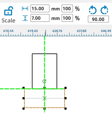
(11) To increase the tightness of the joint, the width of the mortise-tenon is increased by 0.2mm (for laser compensation). First, use the “Rectangle Tool” to draw a rectangle with a width of 9.2mm and a height of 13mm as the mortise-tenon, as shown in Figure 11-41. Then, use the “Rectangle Tool” again to draw a rectangle with a width of 15mm and a height of 6mm as the cap of the mortise-tenon (hereinafter referred to as “mortise cap”). Move the mortise cap to the bottom of the mortise-tenon and align it centrally, as shown in the following figure.
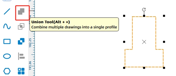
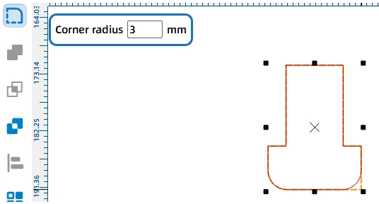
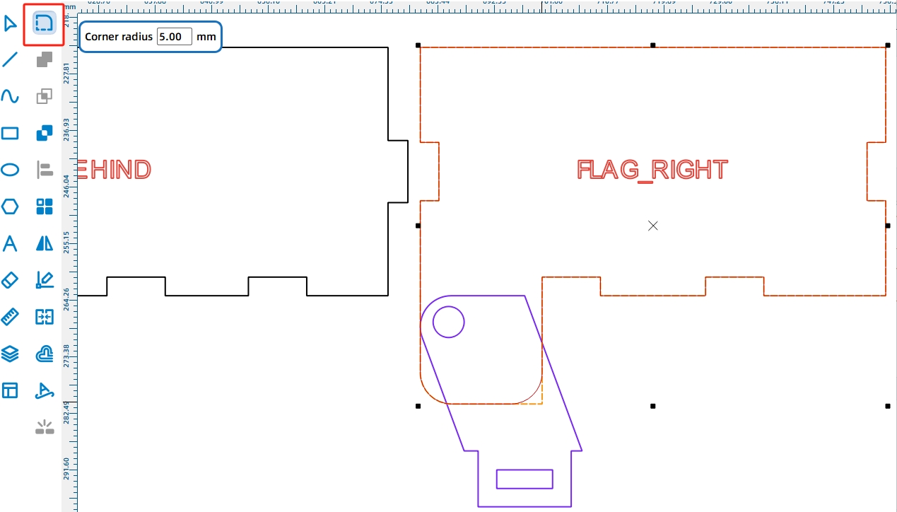
(12) Select the mortise-tenon and the mortise cap with the mouse, and click the “Union” tool in the drawing tools to merge the two rectangles into a single entity, as shown in the following figure. Then, use the “Fillet” tool to make it more rounded and visually appealing. Considering that the width of the mortise-tenon is 9.2mm, set the fillet radius value to 3. Move the mouse to each of the four corners of the mortise-tenon and click to apply the fillet, as shown in the following figure.
After completing a single mortise-tenon, use the Rectangular Array tool to replicate the remaining ones.
(13) Click “Rectangular Array” on the tool menu bar, adjust the parameters, and click “OK,” as shown in the following figure.
With the completion of the drawing for the third motor’s mounting panel, we also need to mark the hole positions for the corresponding mounting plates on the vehicle body, as shown in the following figure.
(14) Draw a rectangle with a width of 20mm and a height of 3mm using the “Rectangle Tool” referring to the width of the fixed board tenon. Click on “Rectangle Array” and set the parameters accordingly. Set the horizontal spacing to 5mm, which is the spacing of the fixed board tenon, and the vertical spacing to the height of the motor cross-section, which is 20mm. Click OK, as shown in the following figure.
(15) Move the replicated hole positions to the center of the TT motor cross-section on the base plate, and align them with the tenon of the fixed plate, as shown in the following figure.
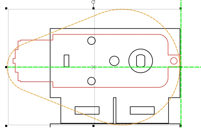
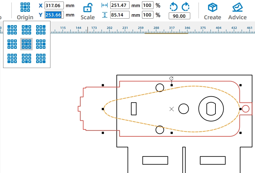
Next, we need to draw a cam that can flip the bucket. In theory, the longer the cam length at the bottom of the bucket, the higher the bucket can rise. However, considering the actual installation space, the length of the cam installed on the motor shaft cannot exceed the length of the TT motor. Additionally, the height of the cam should not exceed the height of the motor fixing plate (25mm).
(16) Click on the “Cam” from the “5. Mechanical Parts” section in the library and drag the graphic into the fixed panel, as shown in the following figure.
(17) Adjust the values in the tool menu bar to 60 and 20 respectively, as shown in the following figure.
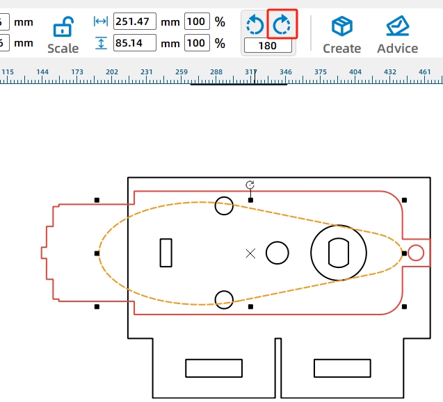
At the same time, rotate the cam so that the larger arc side contacts the bucket, ensuring smoother bucket rotation.
(18) Move the mouse cursor to the rotate button and rotate the cam 180 degrees, as shown in Figure 11-51. Then, adjust the cam’s position slightly to increase the distance from the TT hole position to the top of the cam, as illustrated in the following figure.
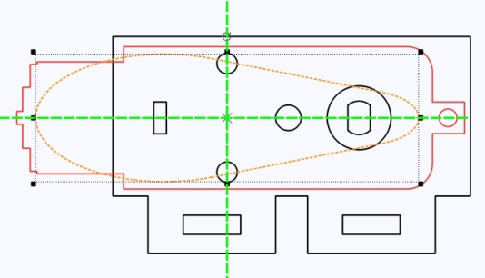
Additionally, in actual assembly, we only need to use the circular holes in the fixed plate, and the excess TT holes can be used for the cam that needs to be installed on the motor.
(19) Press and hold the Ctrl key, click and select the TT holes and the cam in sequence with the mouse, and move them outside the fixed panel, as shown in the following figure. Then, click “Rectangle Array,” set the appropriate parameters, and click “OK” to replicate an identical cam with TT holes, as illustrated in the following figure.
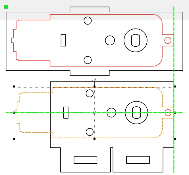
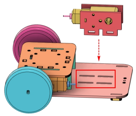
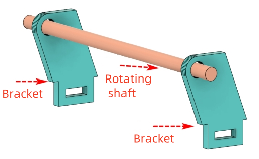
With the power transmission component completed, we will proceed to draw the rotating shaft assembly that drives the bucket’s flipping motion, namely, the rotating shaft base used to secure the round rod onto the body of the vehicle. As shown in the following figure, when the bucket motor rotates the cam, the bucket attached to the round rod will move accordingly.
We first draw a horizontal cross-section of the round rod on the base plate of the vehicle body, which can be used as a reference for subsequent drawing of the rotating shaft base.
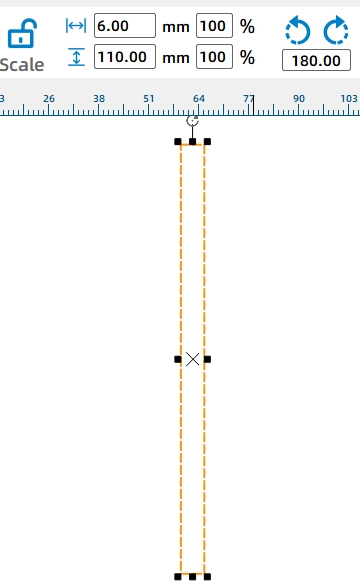
(20) Click on the “Rectangle Tool” and draw a rectangle with a width of 6mm and a height of 110mm on the canvas. To better distinguish this reference, click “More” in the layer settings and select “Purple,” as shown in Figure 11-56. This will change the cross-section to purple, as illustrated in the following figure.
(21) Click and drag the rectangle onto the base panel of the vehicle body, aligning its left end with the vehicle, as shown in the following figure.
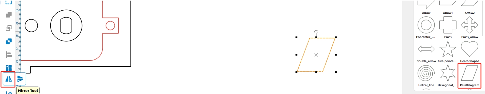
Considering the compactness of components on the base panel of the vehicle body, a parallelogram that can extend outward can be chosen as the rotating shaft bracket. By placing the shaft hole at the left top corner of the parallelogram, it can effectively reduce or avoid friction between the round rod and the bucket motor (the following figure).
(22) Click and select the “Parallelogram” from the “1. Basic Shapes” library in the gallery, drag it onto the canvas, and then click “Flip Horizontal” in the tool menu bar, as shown in the following figure.
To match the height of the rotating shaft bracket with the motor’s fixed panel, we need to set the height of the parallelogram to 25mm.
(23) Click on the “Scale” button in the tool menu bar and change the height value to 25, as shown in the following figure.
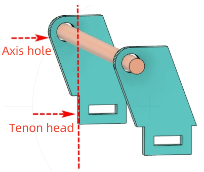
After completing this step, you can start drawing the tenon on the rotating shaft base. Similarly, to ensure the base can be securely fixed to the vehicle body, we will still use the pin connection method (as mentioned in step 3, details omitted).
(24) Click on the “Scale” button in the tool menu bar, unlock the proportions, and then click on the “Rectangle Tool” to draw a rectangle with a width of 15mm and a height of 9mm, as well as a rectangle with a width of 9mm and a height of 3mm, as shown in the following figure.
(25) Select the two rectangles with your mouse, click on the “Align” tool in the drawing toolbar, and successively click “Align Horizontal Centers” and “Align Vertical Centers,” as shown in the following figure.
(26) Move the two rectangles (the tenon with the mortise) to the rotating shaft base and align them centrally with its bottom edge, as shown in the following figure.
(27) While holding down the Ctrl key on your keyboard, select the base panel and the tenon consecutively. Then, click on “Union” to combine them, as shown in the following figure.
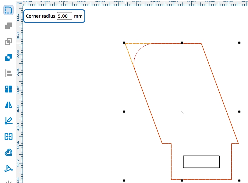
Similarly, due to the rotation of the cam’s arc angle, to ensure the smooth flipping of the bucket on top of the rotating shaft bracket, we need to add a rounded corner to the top corner of the parallelogram.
(28) Click on the “Rounded Corner Tool” in the “Drawing Toolbar,” change the diameter of the rounded corner to 5, move the mouse to the left top corner of the parallelogram, and click to change the corner to a rounded corner, as shown in the following figure.
Now we need to draw the shaft hole that will secure the round rod.
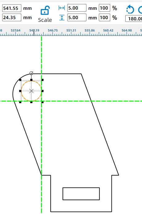
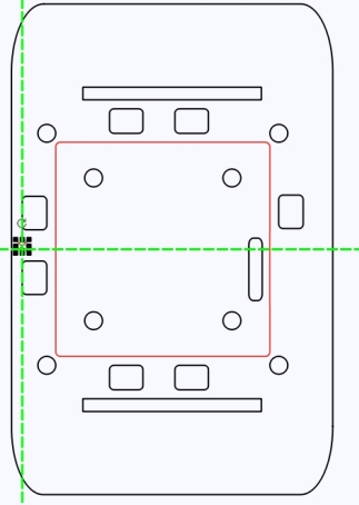
(29) Click and select the “Ellipse Tool” from the “Drawing Toolbar,” draw a perfect circle with a diameter of 6mm, and move the circle to the upper left corner of the base, keeping it parallel to the arc, as shown in the following figure.
In addition, we also need to draw a tenon, which can be directly duplicated from the tenon in the third motor mounting plate.
(30) By using the copy and paste shortcut keys on the keyboard, duplicate a tenon and then move it next to the base panel, as shown in the following figure.
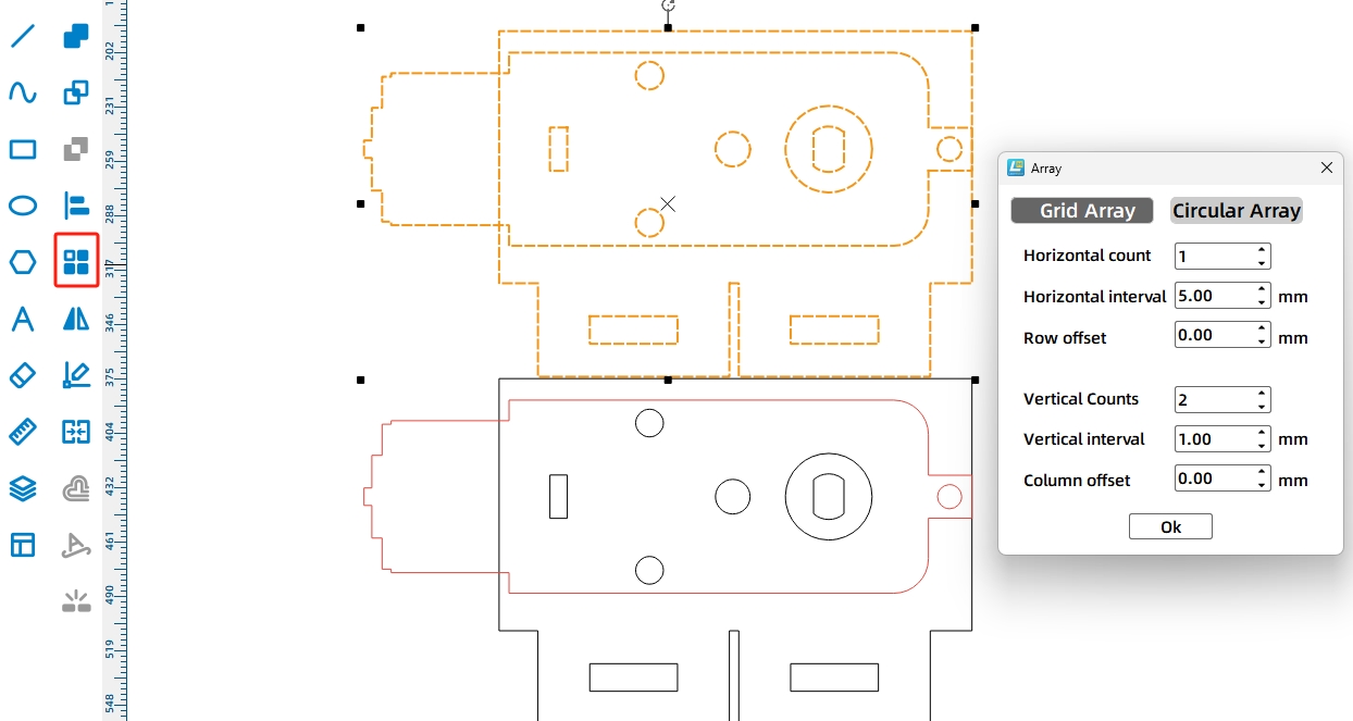
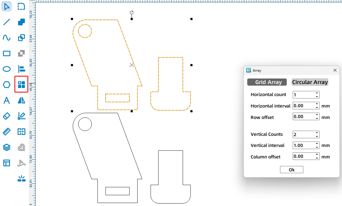
Setting rotating shaft brackets on both ends of the vehicle body allows the round rod to be placed smoothly. Now let’s duplicate a set of rotating shaft bases.
(31) Select the rotating shaft base component with your mouse, click on “Rectangular Array” in the tool menu bar, modify the corresponding parameters in the pop-up window, and click “OK,” as shown in the following figure.
After completing the drawing of the rotating shaft brackets, we need to continue to draw the corresponding fixed hole positions on the vehicle body.
(32) Click on the “Rectangle Tool” in the drawing tools and draw a rectangle with a width of 15mm and a height of 3mm, as shown in the following figure.
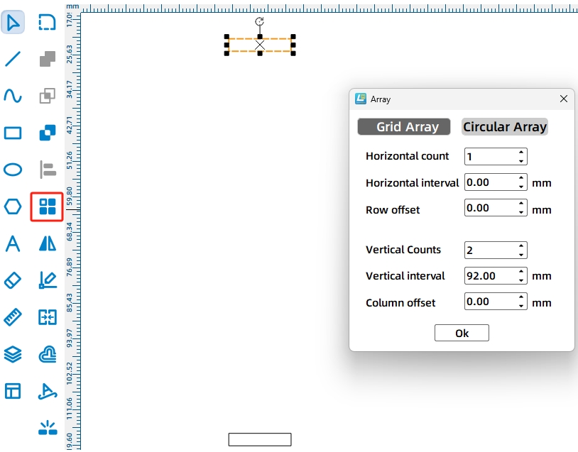
We need to draw two fixing mortises on the vehicle body for the two rotating shaft brackets, as shown in the following figure. Through calculations, we determined that the distance between the mortises is 92mm. This is calculated by subtracting the distance between each mortise and the edge of the vehicle body (110 – 2*9) from the overall width of the vehicle body.
Note: To ensure the stability of the base, we have set the mortise 6mm away from the edge of the vehicle body.
(33) Click on “Rectangular Array” in the tool menu bar, set the vertical spacing parameter value to 92 in the pop-up window, and click “OK,” as shown in the following figure.
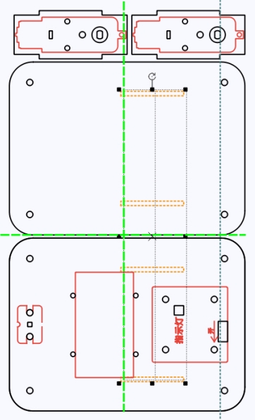
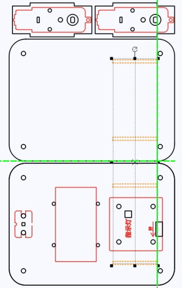
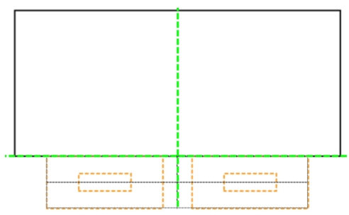
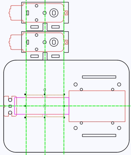
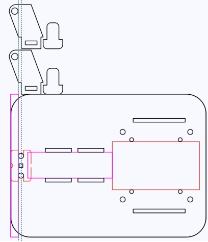
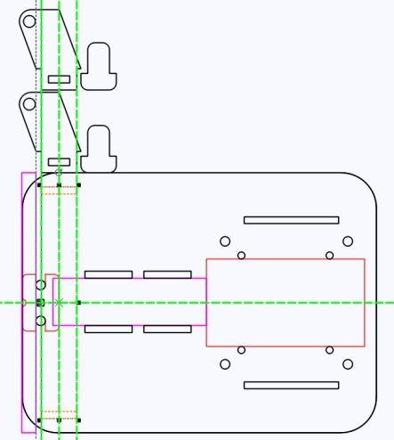
With the mortises drawn, we now need to adjust and finalize their positions on the vehicle body. The positioning of the mortises must consider both the brackets and the vehicle body. We’ll use guidelines to determine the positions.
(34) Move your mouse to the left ruler bar, click and drag a guideline, and move it to the cross-section of the circular shaft, aligning it to the right. Then, select the base panel with your mouse and move it onto the top of the vehicle’s base panel, ensuring that the circular hole in the base aligns with the guideline. Drag another guideline from the left ruler and position it to the left of the base’s tenon, as shown in the following figure.
(35) Select the mortise drawn in step (26), align it to the left of the second guideline, and center it horizontally with the vehicle body, as illustrated in the following figure.
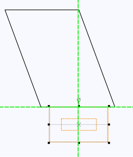
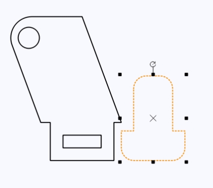
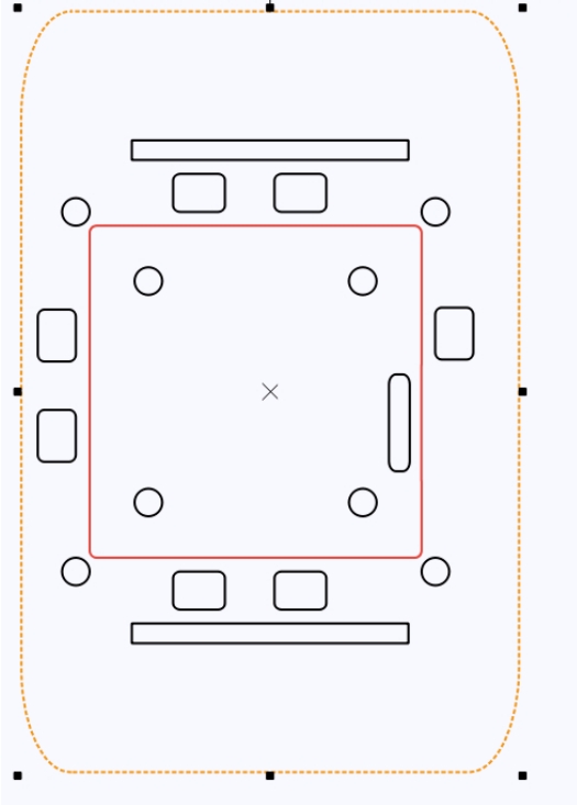
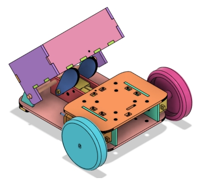
Now, for the final step, we will draw the tipping bucket as shown in the following figure. To determine the length, width, and height of the tipping bucket, we need to know the width and height of the base vehicle (Note: The base vehicle’s width is 150mm and height is 110mm).
Drawing the Tipping Bucket
(1) Click on the top panel of the vehicle body to get its width: 72.00mm, as shown in the following figure. Based on this, we can calculate that the maximum width and height of the tipping bucket’s base are 78.00mm and 110mm respectively.
Additionally, the Energy Stone is projected onto the server by placing a hollow cube with a side length of 60mm. To facilitate easier removal of the Energy Stone, we’ve set the tipping bucket’s height to 40mm and width to 75mm.
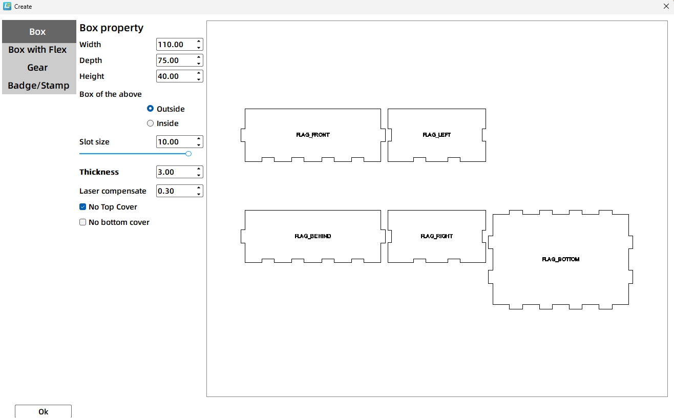
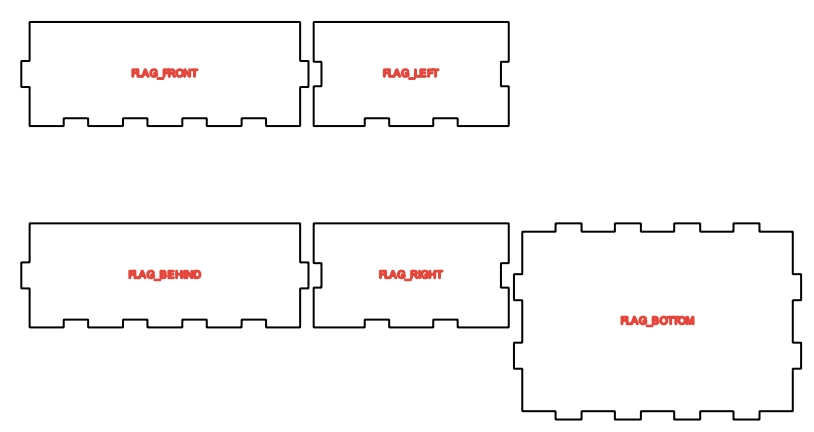
(2) Click “Quick Create” in the tool menu bar. In the pop-up window, set the values for the box’s length, width, and height accordingly, and click “OK”. See Figure 11-78 for specific parameters. The imported canvas effect is shown in the following figure.
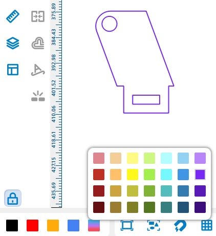
The tipping bucket of the dump truck needs to be connected to the circular shaft, so support legs need to be drawn on the left and right panels of the tipping bucket.
(3) After clicking and selecting the base graphic, copy a rotating shaft bracket using the keyboard combination “Ctrl+C” and “Ctrl+V”. To easily identify this reference, click “More” in “Layer Settings” and select “Purple” to change the color of the reference to purple, as shown in the following figure.
(4) Move the copied base to the bottom of the “right panel” and align it to the left of the panel, as shown in the following figure.
After completing the drawing of the reference object, you can begin to draw the support leg.
(5) Click on “General Cutting (Black)” in the layer settings, then click on the “Rectangle Tool” in the drawing tools. Using the left endpoint at the bottom of the right panel as the starting point, draw a rectangle with the same length as the first tenon on the right panel. There is no fixed height for the support leg, just ensure that the circular hole is in a suitable position on the support leg, as shown in the following figure.
(6) Click on the “Selection Tool” in the drawing tools, hold down the Ctrl key, and click on the support leg and the right panel in sequence. Then, click on “Union” in the drawing tools to merge the graphics, as shown in the following figure.
Considering that the support leg is on the outer side of the pivot bracket, in order to make the support leg look more beautiful, we use the rounding tool to process the support leg.
(7) Click the “Rounding Tool” in the drawing tool, and move the mouse to click on the left and right bottom corners of the support leg’s bottom successively, as shown in the following figure.
The shaft hole in the support leg can be directly applied from the reference pivot bracket.
(8) Click to select the circular hole in the base and click “Universal Cutting” in the bottom layer settings, as shown in the following figure.
After completing the drawing of the support leg on the right panel, we can directly use the cloning method to draw the support leg for the right panel.
(9) After selecting the right panel and circular hole with the mouse, click “Rectangular Array” in the menu toolbar, modify the corresponding values in the pop-up window, and click “OK” as shown in the following figure.
The tilting bucket is fixed to the round shaft through the shaft hole on the support leg. When the tilting bucket is pushed up by the cam, it cannot fall back to its original position due to the angle and its own weight. Therefore, an external force needs to be applied to the tilting bucket, which can be achieved by using a rubber band. In this way, when the cam raises the tilting bucket, the tension of the rubber band increases. After the cam rotates back to its original position, the tilting bucket will be “pulled” back by the elastic force of the rubber band.
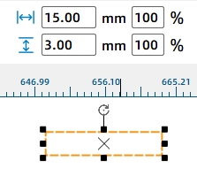
(10) Click the “Ellipse Tool” in the drawing tool, draw a perfect circle with a diameter of 2mm, and move the circle to the center point at the bottom of the rear panel of the tilting bucket truck, as shown in the following figure.
(11) Hold down the Ctrl key on the keyboard, then press the letter keys C and V in sequence to move the copied circular hole to the center of the left end of the top panel, as shown in the following figure.
Finally, after completing the dump truck body, remember to save your file.
(12) Remove unnecessary prompts and other information, click “File” in the toolbar, select “Save,” modify the save path and file name, then click “Save” as shown in the following figure.
Laser Processing
After completing the design and drawing of the blueprint, you can use a laser cutter to cut out the design. We will delete unnecessary auxiliary lines and references, and adjust the layout of the design appropriately to improve the utilization rate of the wood board. Finally, check and confirm the processing parameters, such as the speed and power of the marking and cutting, to ensure they match the cutting material we are using. Once everything is confirmed, click “Start Fabrication.” Once the file is successfully transmitted to the laser cutter, we can immediately begin operating the laser cutter to complete the cutting of the project, as shown in the following figure.
Assembling the Model
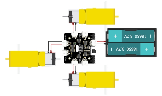
Circuit Wiring
Connect the circuit according to the wiring diagram shown below. Since the rotating speed of the dump truck should not be too fast, for the third TT motor, we choose to use a motor with a 1:220 gear ratio.
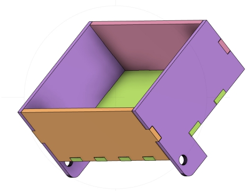
After cutting all the parts for the dump truck, it is necessary to proceed with the assembly of the prototype model.
Structural Assembly
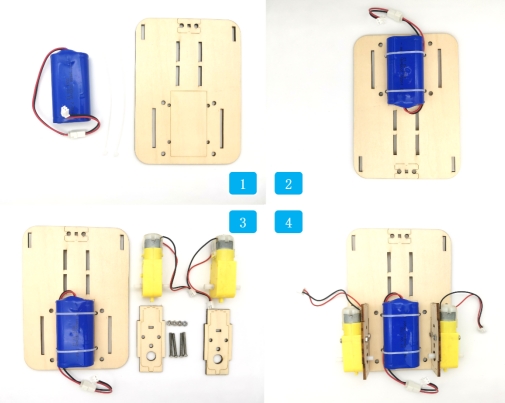
To assemble the dump truck, it is necessary to fix the three TT motors, two 18650 battery packs, and the 2.4G receiver to their respective positions using screws and nuts. The specific steps for assembling the body, rotating mechanism, and tilting bucket are as follows:
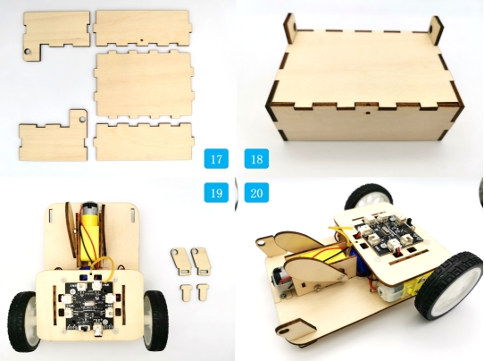
Step 1: Identify the vehicle base plate, cable ties, and batteries.
Step 2: Use cable ties to secure the batteries onto the vehicle base.
Step 3: Locate the wooden plate for fixing the tire motor, the TT motor with a 1:220 gear ratio, and the corresponding screws and nuts.
Step 4: Mount the motor onto the fixing plate and then secure it to the vehicle base plate.
Step 5: Retrieve the mounting plate for the third motor, the TT motor, and the corresponding screws and nuts.
Step 6: Install the motor onto the mounting plate, and then secure it to the vehicle’s base plate.
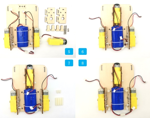
Step 7: Take out the hexagonal column and its accompanying screws.
Step 8: Fix the hexagonal column onto the corresponding holes on the base plate.
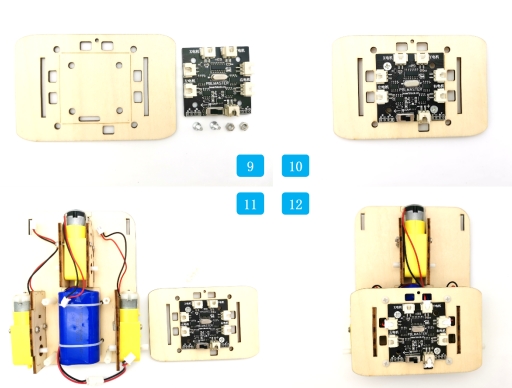
Step 9: Locate the control board, the mounting plate for the control board, and the corresponding screws and nuts.
Step 10: Secure the control board to the mounting plate.
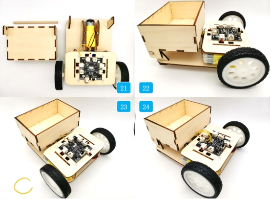
Step 11: Retrieve the previously assembled vehicle base plate and the hexagonal column screws.
Step 12: First, thread the connecting wires of the electronic components on the base plate through the top plate and connect them to the control board. Then, use screws to fix the top and bottom plates of the vehicle’s body.
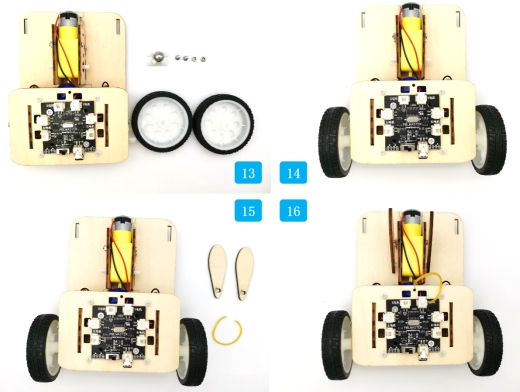
Step 13: Retrieve the caster wheels, tires, and corresponding screws and nuts.
Step 14: Fix the caster wheels to the front of the vehicle and install the tires onto the rotating shaft of the vehicle’s motors.
Step 15: Take out the cam and the cut rubber band.
Step 16: Fix the cam to the rotating shaft of the third motor and thread the rubber band through the circular hole on the top plate, tying a knot at the end.
Step 17: Locate the front, rear, left, right, and bottom panels of the tilting bucket.
Step 18: Assemble all the panels of the tilting bucket together.
Step 19: Find the base components of the rotating mechanism.
Step 20: Fix the base to the front end of the vehicle’s body.
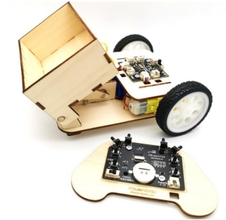
Step 21: Retrieve the tilting bucket and the round rod.
Step 22: Place the tilting bucket outside the rotating base and secure it with the round rod.
Step 23: Take the cut rubber band.
Step 24: Fix the rubber band onto the tilting bucket and tie a knot with the rubber band on the vehicle’s body.
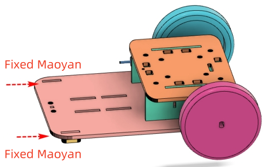
And here it is! The dump truck is now fully assembled. You can now take out the remote control and start using it to transport items! Enjoy your newly assembled dump truck!
Summary:
During the dump truck project, we learned to modify existing drawings, appreciate the role of references in modeling, and master tools like rectangular arrays, rounding, and alignment in the software. Next, it’s the final challenge – lifting the energy stone.
Thought Expansion
For this dump truck model, we used the basic “right-angle box” function in LaserMaker. Do you have any better ideas for the design of the dump? Also, though we’ve considered the motor speed affecting the dump’s tilt and used a low-speed TT motor, the dump still dumps items quickly due to inertia. Do you have any good ways to improve this? Looking forward to your creative ideas!


.png "laser cutter Globle")


