I. Introduction
II. List of Materials
单击 “编辑” 按钮更改此文本。这是测试文本。
III. Laser Modeling
1. Drawing the Shape
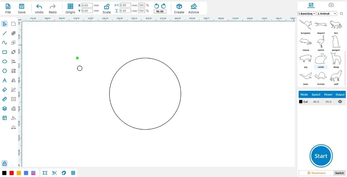
Tips: When using the [Rectangle] and [Ellipse] tools, holding down the Ctrl key while dragging the shape will allow you to draw a shape with a 1:1 width-to-height ratio, resulting in a square or circular shape.
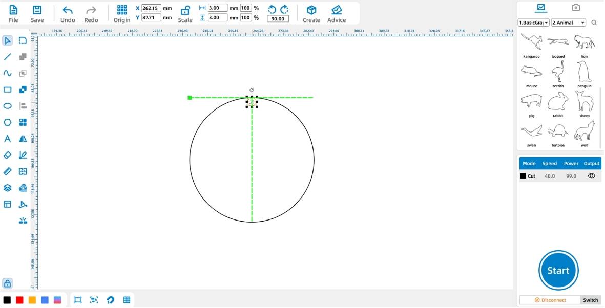
(2) Click the [Select] tool from the left-side [Drawing Toolbar] and place Circle ① directly above Circle ②, as shown in the figure below:
2. Drawing Graphical Elements
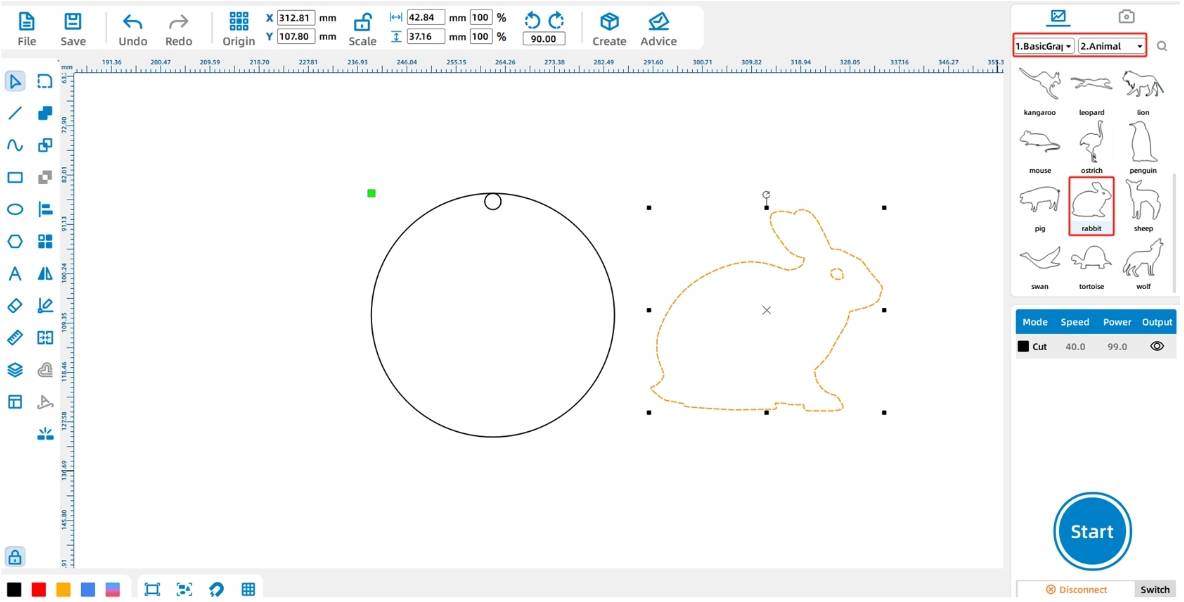
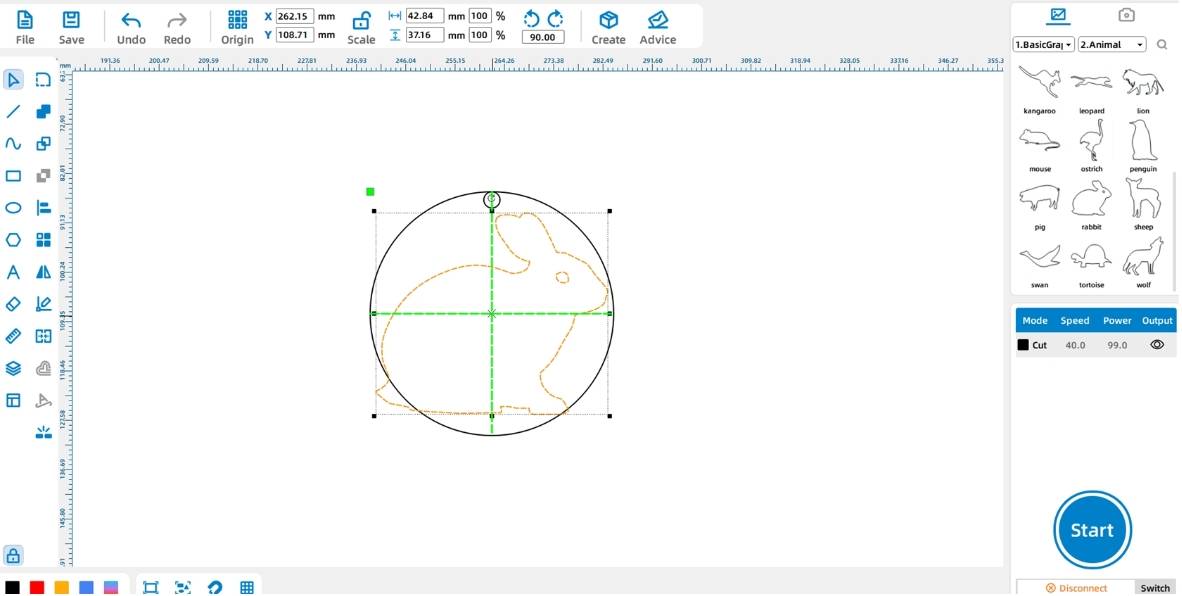
3. Laser Processing
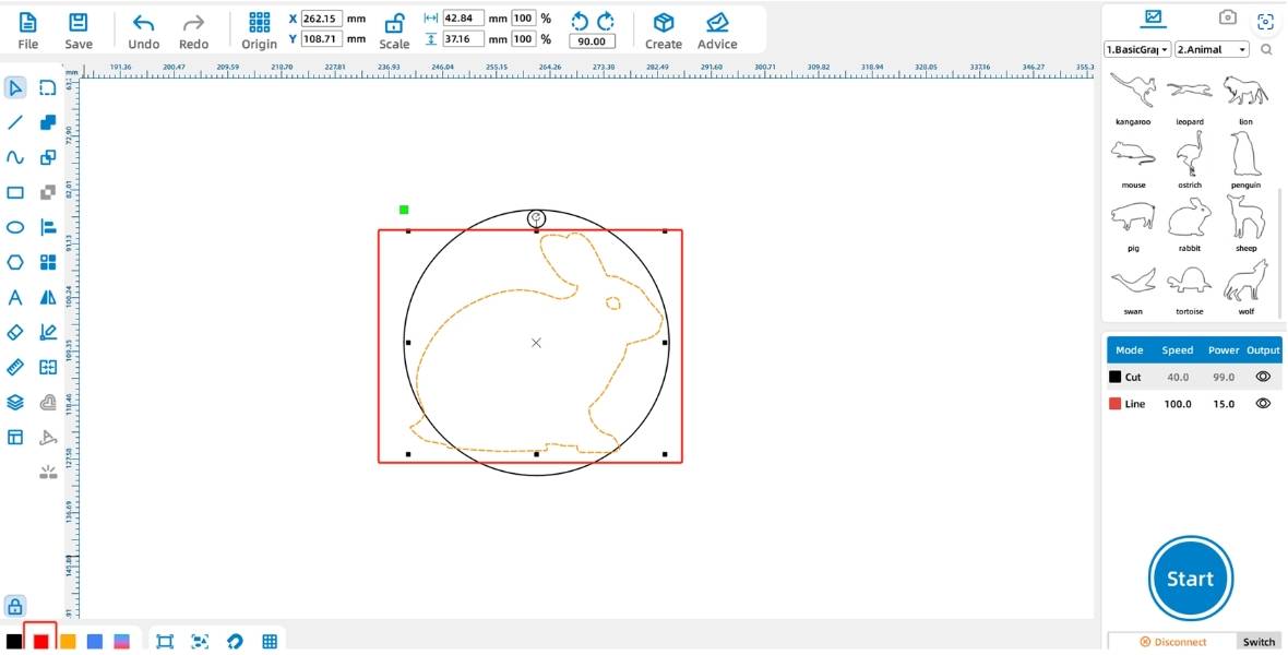
Tips: The black, red, yellow, and blue layers in the [Layer Palette] have default processing techniques, which are cutting, outlining, shallow engraving, and deep engraving, respectively.
(2) Double-click the black layer in the lower-right [Processing Panel] and set the material, thickness, and technique to basswood board, 3mm, and cutting, respectively. For the red layer, set the material, thickness, and technique to basswood board, 3mm, and outlining. Left-click the black layer and drag it to the bottom of the layer stack, as shown in the figure below:
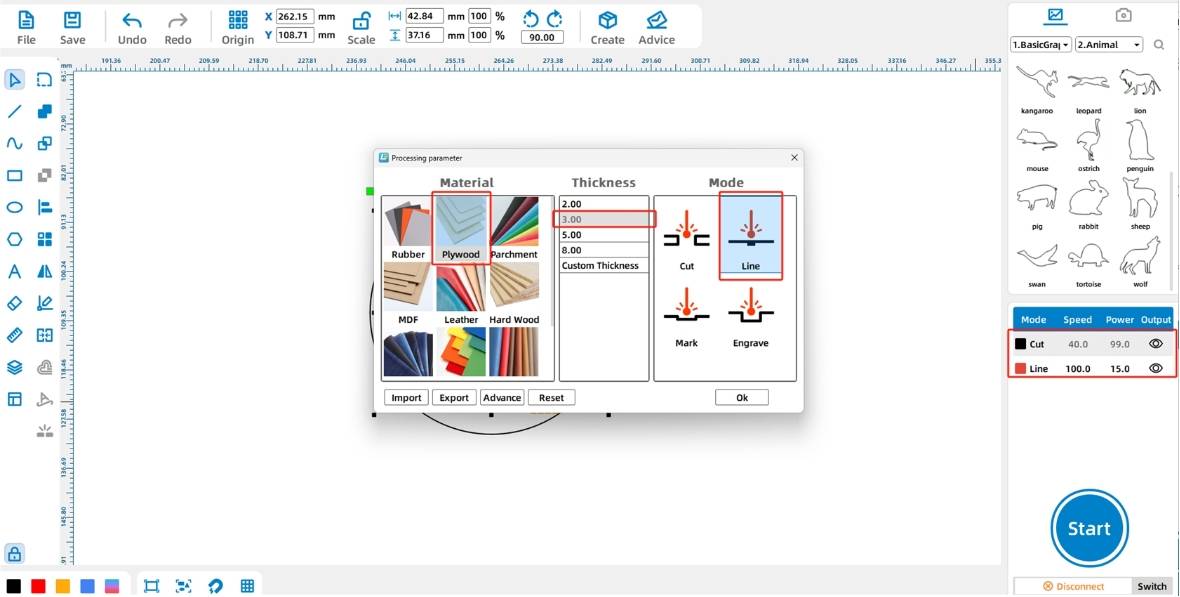
Tips: The device processes the layers in the order they are stacked in the [Processing Panel], from top to bottom. Generally, we place the cutting layer at the bottom to ensure the integrity of the workpiece.
(3) Click the “Switch” button in the lower-right [Processing Panel] to enter the device management interface. Click the “Test” icon in the row labeled “usb” and proceed when the “Communication Successful” message pops up, as shown in the figure below:
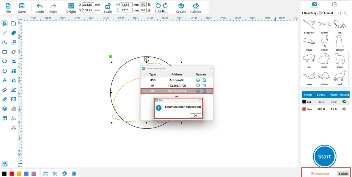
Tips: Before connecting the device, make sure to connect the PC-USB cable from the toolbox directly to the PC interface of the device and the USB port of the computer, and insert the dongle from the toolbox into the USB port of the computer.
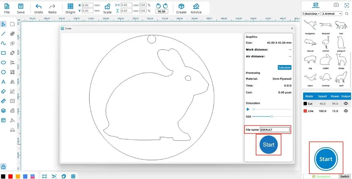
(4) Click the “Start” button in the lower-right [Processing Panel] to upload the file to the device, as shown in the figure below:
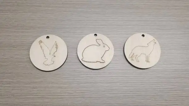
IV. Work Presentation
V. Conclusion
Browse Thunder Laser
Bolt >


.png) International
International
 United States
 Brasil
 Canada
 Costa Rica
 Česká
Česká
 Ελλάδα
 Polska
 Ireland
 Portugal
 Lietuva
 Россия
 Deutschland
 Britain
 Україна
 France
 Sverige
 Italia
 Norway
 Denmark
 Romania
 한국
한국
 中国
中国
 ประเทศไทย
 中国香港
中国香港
 Israel
 中國臺灣
中國臺灣
 India
India
 پاکستان
 پශ්රී ලංකා
 ジャパン
ジャパン
 Australia
 New Zealand
 South Africa