Project Origin:
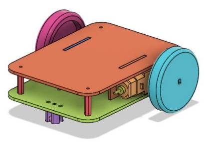
For the amusement park expansion project on Planet M, designers need to create three racing cars: a collection vehicle, a dumper, and a crane. To adapt to the competition rules and reduce redundant design, they have decided to first create a universal base vehicle body.
Let’s embark on this new design journey together.
Determining the Design Plan
Observation and Analysis
The vehicle body designed for this project is as shown in the figure. It consists of an upper and lower plate, with a motor mounting plate in between. Paired with two motors, wheels, and a caster wheel at the front, the vehicle body will be capable of moving. Once the vehicle body is complete, we’ll use the OSROBOT open-source robot remote control kit provided by the manufacturing factory to install the control board, battery, and other components, enabling remote-controlled movement. The focus of this section is how to precisely fit the tenon size of the motor mounting plate with the mortise size of the vehicle body plates.
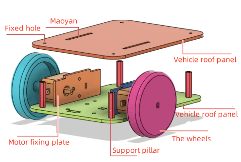
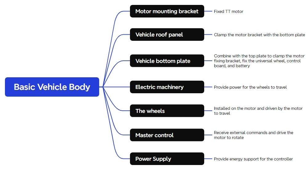
Based on the analysis mentioned above, we can break down the design of the vehicle body into the following components, as shown in the following figure.
Materials List
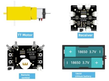
A total of 7 materials are involved in this project, as shown in the the following Table.
Number
Name
Quantity
1
2.4G Remote Controller (with Battery)
1
2
2.4G Receiver
1
3
TT Motor (1:120)
2
4
18650 Battery (with Cable)
1
5
Basswood Plywood (40cm x 60cm x 3mm)
1
6
M3/M4 Screws, Nuts, and Nylon Standoffs
Several
Number | Name | Quantity |
1 | 2.4G Remote Controller (with Battery) | 1 |
2 | 2.4G Receiver | 1 |
3 | TT Motor (1:120) | 2 |
4 | 18650 Battery (with Cable) | 1 |
5 | Basswood Plywood (40cm x 60cm x 3mm) | 1 |
6 | M3/M4 Screws, Nuts, and Nylon Standoffs | Several |
Vehicle Structure Design
With the selected materials and components, we now proceed to designing the structure of the vehicle body.
Creating a Parts List
First, based on the observation and analysis of the vehicle body and the components listed in the materials inventory, we can determine the structural parts required for the design. The design of this project comprises three main structural parts, as shown in the following Table.
Part No. | Part Name | Quantity | Function |
1 | Motor Mounting Plate | 2 | Secures TT motors |
2 | Top Body Plate | 1 | Combines with the bottom plate to sandwich the motor mounting plate |
3 | Bottom Body Plate | 1 | Combines with the top plate to sandwich the motor mounting plate, secures the caster wheel, control board, and battery |
Laser Modeling
The parts list provides us with a step-by-step outline for our laser modeling design. Now we can proceed with the laser modeling process.
Draw the motor mounting plate
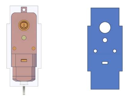
The operation of a vehicle definitely relies on a motor that provides power. Now, a fixing plate for the motor needs to be drawn. In the LaserMaker library, the graphic of a TT motor is already provided. Referring to the above figure, a large rectangle and two small rectangles should be drawn first. After combining the three rectangles, they will be assembled with the TT motor holes to form the motor fixing plate.
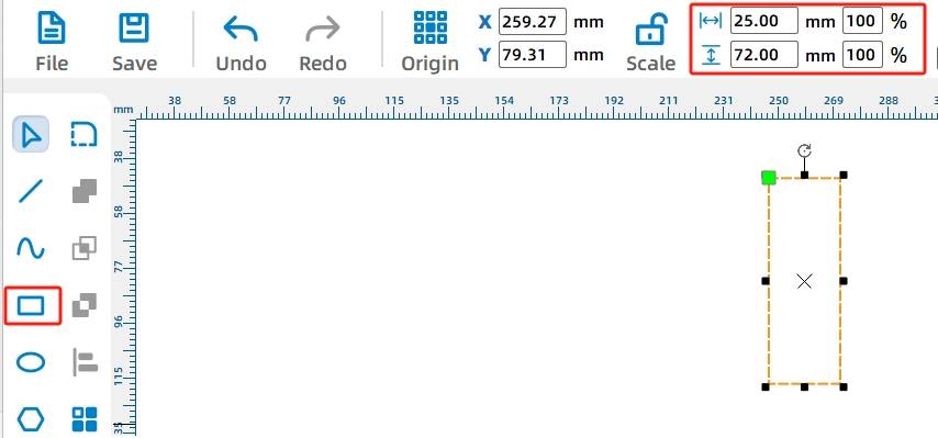
(1) Select the “Rectangle Tool” in the drawing toolbar and draw a rectangle with a width of 25mm and a height of 72mm, as shown in the following figure.
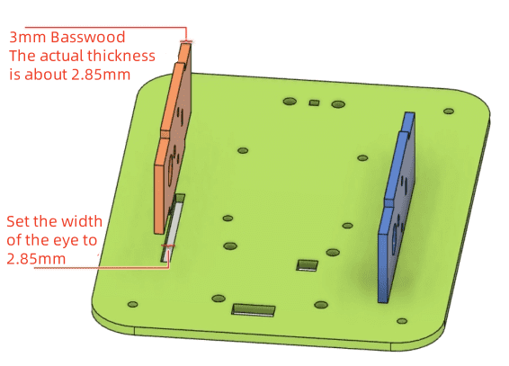
Since the motor fixing plate connects to the top and bottom plates of the vehicle body through a mortise and tenon joint, it is necessary to add a tenon on each side of the rectangle. Considering the actual thickness of the 3mm-thick basswood board is around 2.85mm, coupled with laser cutting loss, the width of the rectangular tenon is set to 2.85mm. The height of the rectangular tenon should be smaller than the height of the rectangular plate drawn in the previous step. The purpose of the rectangular tenon is to insert into the mortises of the top and bottom vehicle body plates, allowing them to clamp the motor fixing plate securely. As shown in the following figure.
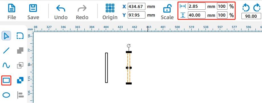
(2) In the drawing toolbar, select the “Rectangle Tool” and draw two rectangles with a width of 2.85mm and a height of 40mm, respectively. As shown in the following figure.
(3) Next, use the “Selection Tool” to select a rectangular mortise, drag and move it to the left side of the rectangular motor fixing plate, and align it. As shown in the following figure.
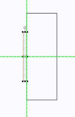
Next, use the Union Tool to merge the tenon with the rectangular motor fixing plate.
(4) Select both rectangles using the Selection Tool, then use the “Union Tool” in the drawing toolbar to merge the two shapes into a single entity. As shown in the following figure.
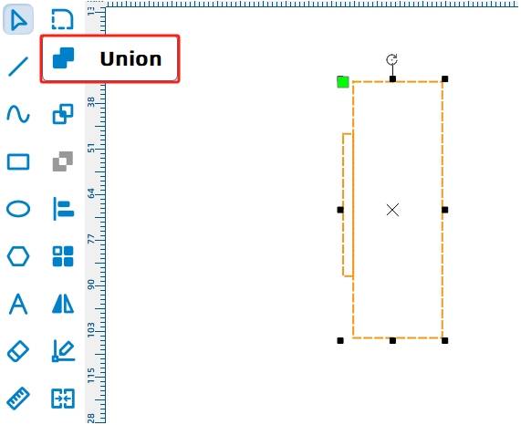
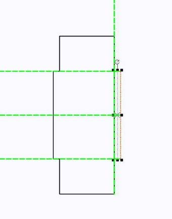
The left tenon has been merged with the motor fixing plate. Using the same method, merge the fixing plate with the right tenon.
(5) Next, use the “Selection Tool” to select the other rectangular mortise, move it to the right side of the rectangular motor fixing plate, and align it. As shown in the following figure.
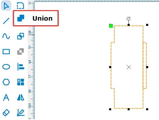
(6) Use the selection tool to select both rectangles simultaneously, click the “Union Tool” in the drawing toolbar, and then you can merge the two shapes together. As shown in the following figure.
(7) To add the mounting hole for the TT motor on the fixing plate, click on the library, locate “9. Open-Source Robot Hardware”, select “TT Motor”, and drag it onto the canvas, as shown in the following figure.
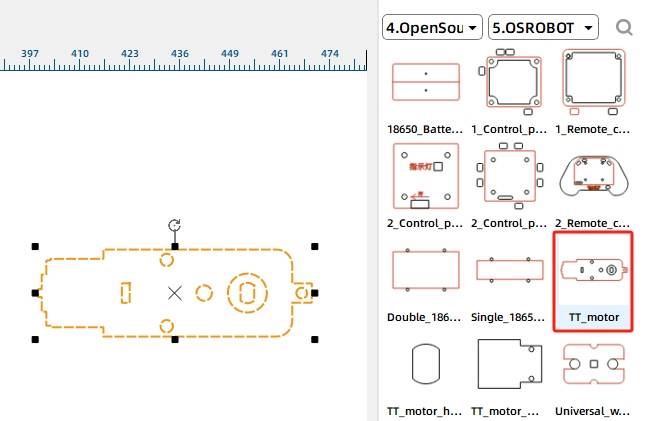
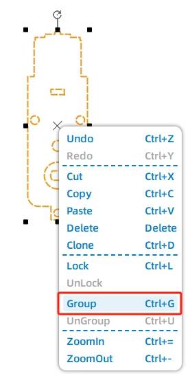
(8) To facilitate alignment, rotate the TT motor hole pattern 90° and group it together. You can use the keyboard shortcut “Ctrl+G” or right-click and select “Group” as shown in the following figure.

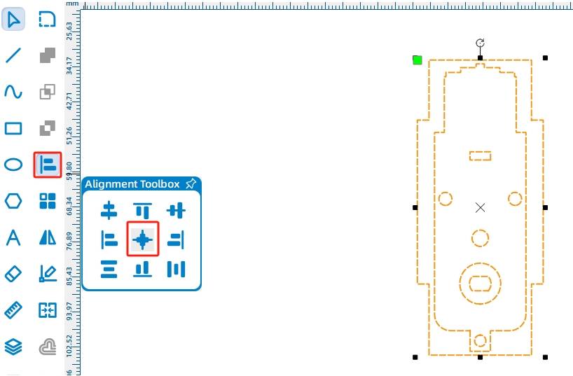
(9) Select both the TT motor and the motor fixing plate simultaneously, and click on “Vertical Center Alignment” and “Horizontal Center Alignment” from the “Alignment Toolbox” in the drawing toolbar. As shown in the following figure.
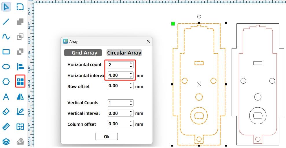
(10) As this chassis will use two TT motors, it requires two TT motor fixing plates. Here, we will replicate the second motor fixing plate using a rectangular array method.
Select the TT motor fixing plate, click on “Rectangular Array” in the menu toolbar, input “Number of Horizontal Rows: 2”, “Horizontal Spacing: 10”, “Number of Vertical Rows: 1”, and set all other values to “0”. Click “OK” to obtain the second motor fixing plate. As shown in the following figure.
- Drawing the Top Plate of the Chassis
With the motor fixing plates designed, we will now proceed to design the top and bottom plates of the chassis, and we need to add mortise for the motor fixing plates and four fixing holes in the chassis plates.
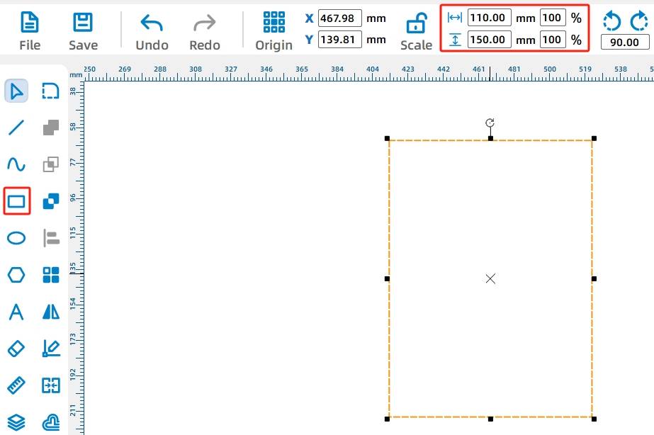
(1) Select the “Rectangle Tool” in the drawing menu bar and draw a rectangle of any size. Then, open the “Proportional Scaling Tool” in the menu toolbar and input a width of “110mm” and a height of “150mm”. As shown in the following figure.
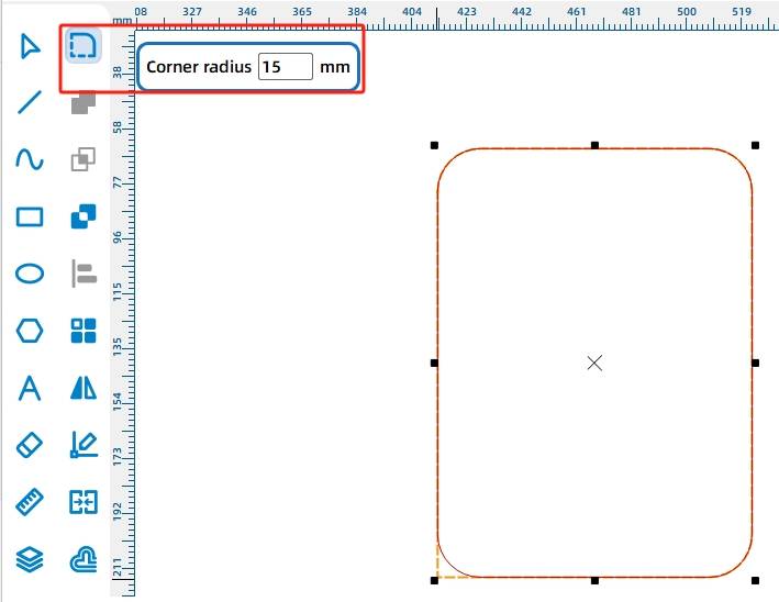
(2) Select the rectangular chassis plate, click on the “Rounded Corner Tool” in the drawing toolbar, enter the rounding parameter “15” in the “Radius” field, and click on each of the four right angles of the rectangle to modify them into rounded corners, as shown in the following figure.
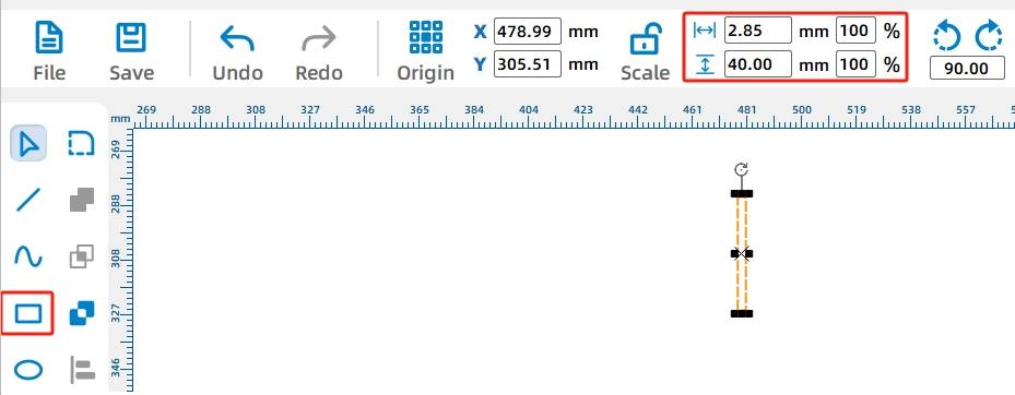
(3) After designing the outline of the chassis plate, we now need to add mortises for the motor fixing plates. Select the “Rectangle Tool” in the drawing toolbar and draw an arbitrary rectangle. Then, ensure that “Proportional Scaling” is activated in the menu toolbar, and set the rectangle dimensions to “Width: 2.85mm, Height: 40mm”. This will create a mortise, as shown in the following figure.
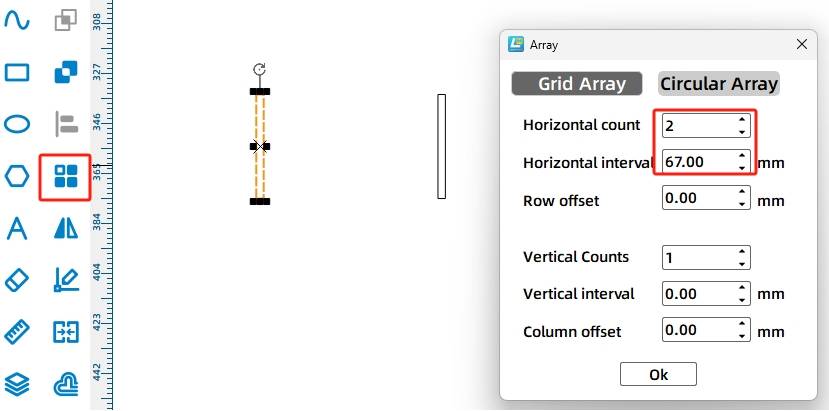
(4) Now we need to add the second mortise, which requires determining the distance between the two mortises. Since a 18650 battery needs to be placed in the middle of the chassis, and the battery’s width is 65mm, we can set the distance between the two mortises slightly larger at 67mm.
Select the rectangular mortise and then choose the “Rectangular Array Tool” to set the horizontal count to “2”, horizontal spacing to “67”mm, vertical count to “1”, and all other parameter values to “0”. This will give us the second mortise. As shown in the following figure.
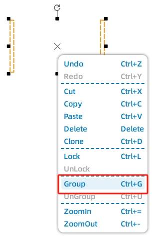
(5) To place the two mortises on the chassis plate, we first need to group them. Select the mortise shapes, press the keyboard combination “Ctrl+G” or right-click and select “Group” as shown in the following figure.
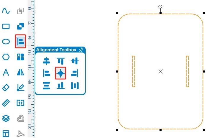
(6) Select both the chassis top plate and the mortise shapes simultaneously. Click on “Vertical Center Alignment” and “Horizontal Center Alignment” in the “Alignment Toolbox” in the drawing toolbar. This will center the mortises in the chassis. As shown inn the following figure.
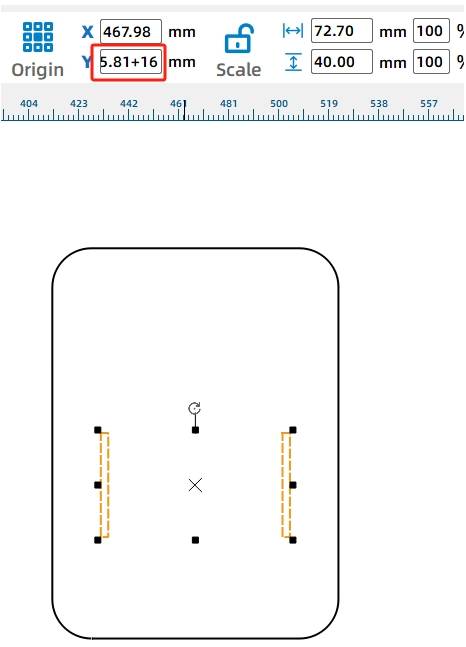
(7) Motors are typically installed at the rear of the chassis, and after calculation, it is most suitable to move the mortises down by 16mm.
Select the mortise shapes, then locate the Y-coordinate in the top menu toolbar. In this software, the Y-axis coordinate rule is that as the numerical value increases, the graphic position moves downward. Input [+16] to the existing value in the box, and this will vertically move the mortises down by 16mm. As shown in the following figure.
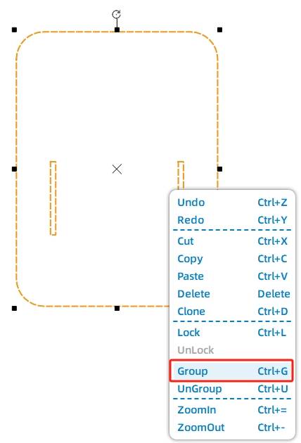
(8) Select the chassis plate graphic with the shifted mortises and group them together, as shown in the following figure.
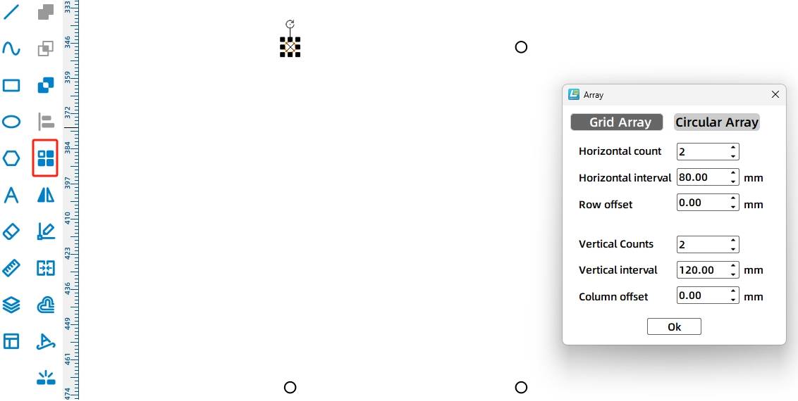
(9) With the mortises designed, we now need to add fixing holes to the four corners of the chassis. In the drawing toolbar, select the “Ellipse Tool” to draw a random circle. Then, in the menu toolbar, set the width and height of the circle to “4”mm. Finally, choose the “Rectangular Array Tool” and set the horizontal count to “2,” horizontal spacing to “80”mm, vertical count to “2,” and vertical spacing to “120”mm. Click “OK” to obtain four fixing holes, as shown in the following figure.
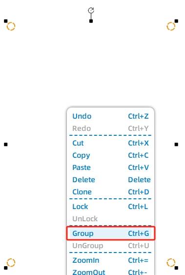
(10) Select the four fixing holes and group them together. As shown in the following figure.
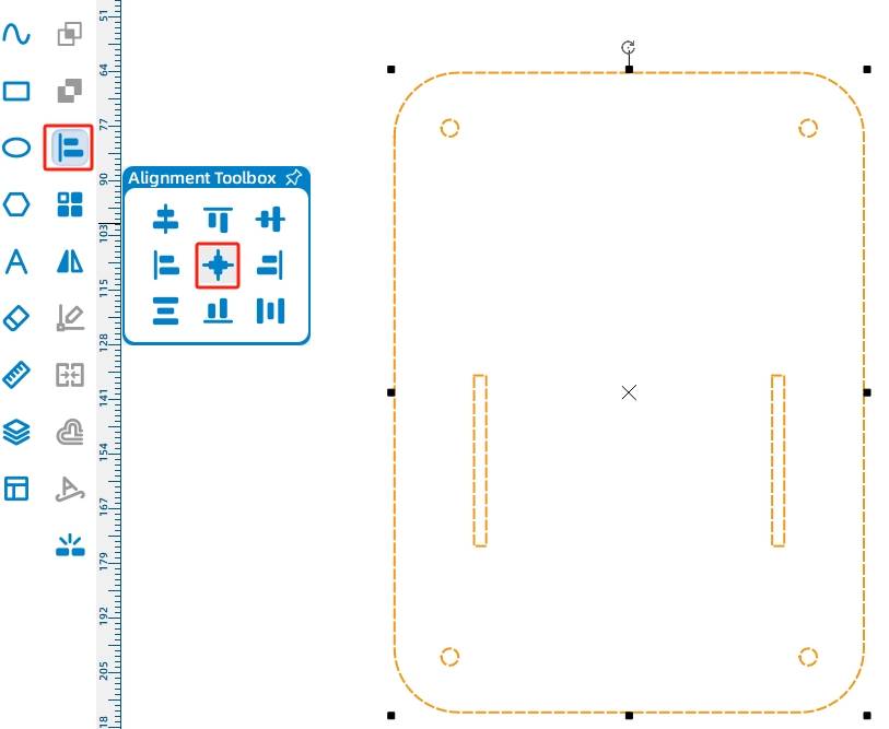
(11) Now, we need to center the screw holes with the chassis plate. Select both the chassis top plate graphic and the circular hole graphics (but do not select the mortises). Use the “Vertical Center Alignment” and “Horizontal Center Alignment” tools from the “Alignment Toolbox” to align the screw holes with the chassis plate. As shown in the following figure.
- Drawing the Chassis Bottom Plate
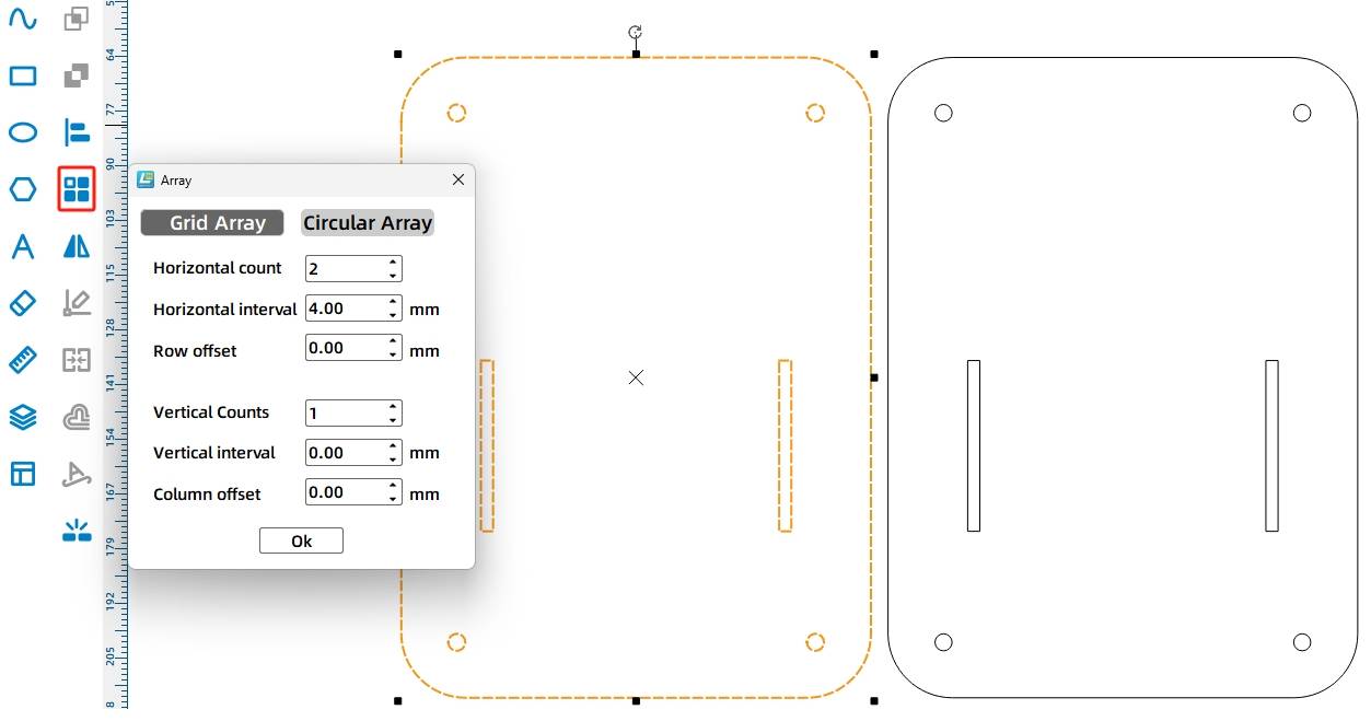
(1) After the design of the chassis top plate is completed, we can use the rectangular array method to obtain the chassis bottom plate. Select the chassis top plate and choose the “Rectangular Array Tool” to set the horizontal count to “2,” horizontal spacing to “4”mm, and vertical count to “1,” as shown in the following figure.
(2) To allow the chassis to move flexibly, we also need to add a caster wheel to the chassis bottom plate. From the library, under “9.0 Open-Source Robot Hardware,” select the “Caster Wheel” and drag it onto the canvas, as shown in in the following figure.
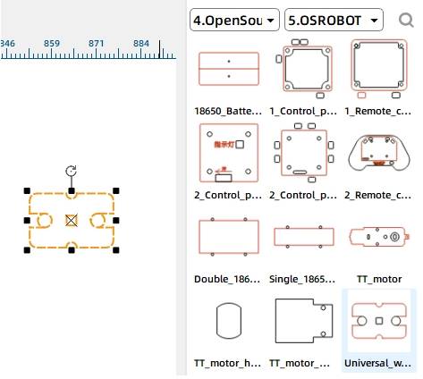
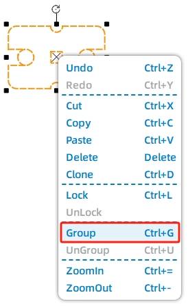
(3) Select the caster wheel graphic and group it together, as shown in the following figure.
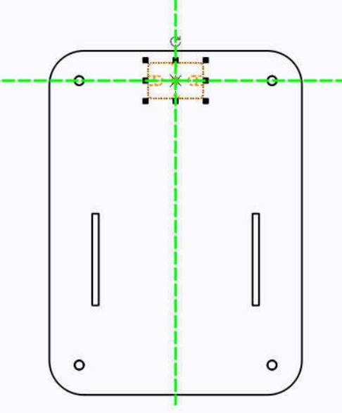
(4) Click on the caster wheel and, using the green guidelines as a reference, drag it so that the center of the caster wheel aligns horizontally with the center of the circular holes and vertically with the center of the chassis bottom plate, as shown in the following figure.
After adding the caster wheel, it’s necessary to include the control board and battery mounting positions on the chassis bottom plate.
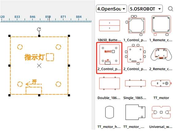
(5) From the library, under “Open-Source Robot Hardware,” select the “2.0 Control Board (Internal)” and drag it onto the canvas, as shown in the following figure.
(6) Right-click to select the “2.0 Control Board” graphic. Using the green guidelines as a reference, drag it so that the bottom of the control board aligns horizontally with the bottom of the circular holes and vertically with the center of the chassis bottom plate, as shown in the following figure.
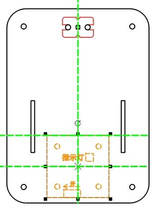
(7) Select “Double 18650 Battery” from the “Open-Source Robot Hardware” library and drag it onto the canvas, as shown in the following figure.
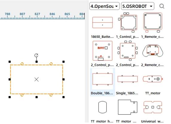
(8) Click to select the “Double 18650 Battery” graphic, use the green guidelines as a reference, and drag it to align vertically with the center of the chassis bottom plate, above the “2.0 Control Board.” The chassis bottom plate is now complete, as shown in the following figure.
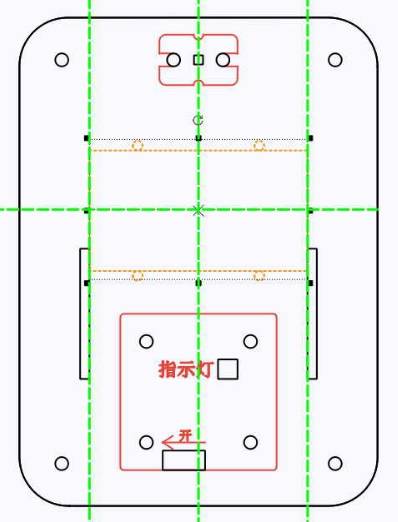
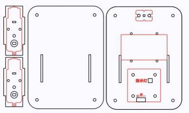
With this, the design of the chassis is complete. Finally, the completed drawing is laid out as shown in the following figure.
Laser Processing
After completing the drawing design, we can set up the processing parameters for cutting.
Setting Parameters
(1) Outlining
Double-click on the red block in the processing area. For material, select 1. Basswood Plywood. For processing method, select Outlining. Set the processing thickness to 0.10, and click OK.
(2) Cutting
Double-click on the black block in the processing area. For material, select 1. Basswood Plywood. For processing method, select Cutting. Set the processing thickness to 3.00, and click OK.
Starting Fabrication
Turn on the power switch of the laser cutting machine and turn on the laser. Wait for the “Start Fabrication” button to turn blue, then click it. Once the drawing is uploaded to the laser cutting machine, press the Start button on the laser cutting machine’s panel to begin cutting.
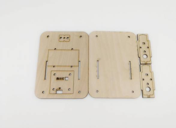
Model Assembly
After cutting, the next step is to assemble the model.
Circuit Wiring
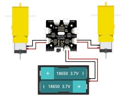
Once the model is assembled, we need to connect the circuit according to the wiring diagram in the following figure. Then the car can be remotely controlled for driving.
Once you have the chassis parts, it’s time to start assembling the model.
Structural Assembly
Step 1: Identify the caster wheel, chassis bottom plate, M4 screws, and nuts.
Step 2: Install the caster wheel onto the chassis bottom plate (underside) using M4 screws.
Step 3: Tighten the caster wheel using M4 nuts.
Step 4: Take out the chassis bottom plate with the installed caster wheel, M4 nylon pillars, and nuts.
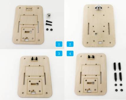
Step 5: Insert the nylon pillars into the round holes at the four corners of the chassis plate and tighten them with nuts.
Step 6: Locate the receiver board, 4 short M4 screws, and M4 nuts.
Step 7: Use the screws to secure the receiver board onto the square section of the chassis bottom plate.
Step 8: Locate the TT motor, motor mounting bracket, M3 screws, and M3 nuts;
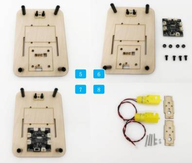
Step 9: Use M3 screws and nuts to secure the motors onto the motor brackets, ensuring the nuts are on the inside of the wood (to avoid the M3 screws protruding and interfering with the wheel installation).
Step 10: Locate the two motors from Step 9 and the chassis plate from Step 7.
Step 11: Attach the motor brackets to the chassis plate.
Step 12: Locate the chassis plate from Step 11, the 18650 battery, and the cable ties.
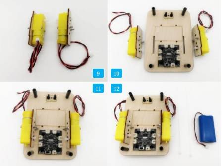
Step 13: Secure the 18650 battery to the rectangular area of the chassis plate using cable ties.
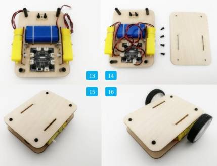
Step 14: Locate the chassis plate from Step 13, the chassis top plate, 4 short M4 screws, the receiver board, and wire the components according to the wiring diagram in Figure 9-39.
Step 15: Use screws to attach the chassis top plate to the chassis bottom plate.
Step 16: The car chassis installation is complete.
Summary
Looking back at the design of the car, in addition to mastering the basic drawing and design skills of a laser cutter, the focus of this section is on the positioning and sizing of the tenons and mortises for the motor mounting plate. By calculating the parameters, the mortise pattern is subjected to coordinate axis calculations based on these parameters, ultimately achieving precise alignment between the tenons and mortises. As shown in the following figure.

With the completion of the car body, designers are eager to upgrade it with new functionalities. Let’s dive into the next design phase together!
Thought Expansion
Inspired by the ingenious and unique usage of ancient mortise and tenon joints, consider how we can design the top plate, bottom plate, and motor mounting plate of this car body to achieve assembly and fixation without using a single screw. Let’s put our heads together and brainstorm some ideas!
Browse Thunder Laser Bolt >



.png) International
International
 United States
 Brasil
 Canada
 Costa Rica
 Česká
Česká
 Ελλάδα
 Polska
 Ireland
 Portugal
 Lietuva
 Россия
 Deutschland
 Britain
 Україна
 France
 Sverige
 Italia
 Norway
 Denmark
 Romania
 한국
한국
 中国
中国
 ประเทศไทย
 中国香港
中国香港
 Israel
 中國臺灣
中國臺灣
 India
India
 پاکستان
 پශ්රී ලංකා
 ジャパン
ジャパン
 Australia
 New Zealand
 South Africa