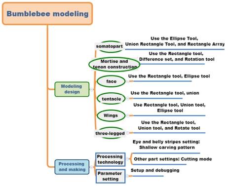
Master the comprehensive application methods of “Rectangle tool”, “Ellipse tool”, “Rectangular array” tool, “Alignment guide line”, “difference set”, “union” and “rotation” functions.
Thinking training
Design thinking
(1) It can decompose and compose irregular objects.
(2) Understand the method of section drawing and solid model building of symmetrical objects.
(3) Master the form, graphic drawing and solid structure design methods of straight mortise and tenon joints.
Computational thinking
(1) Calculate the insect body and legs and other components, and design them in the laser cutting modeling software.
(2) To master the feasibility calculation of the production of thin limb parts in laser cutting modeling software.
Engineering thinking
(1) Master the technical treatment of the mortise and tenon structure of the insect joint and the Angle of the inclined plane.
(2) Verify the feasibility of thin part cutting, experiment on the effect, and obtain the empirical parameter values.
Social responsibility and moral literacy
In practice, you can imitate the works of others in style, and you must do improved innovation when creating.
2. Application scenario
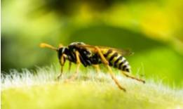
Bumblebees are large, bloated, with small wings and disproportionate bodies, making them slow and clumsy when crawling. The body appearance of the adult bumblebee also has the standard features of insects, including a head, chest, abdomen, three pairs of legs and a pair of antennae, compound eyes, and wings. The adult body is mostly black, yellow, brown 3 colors, or a single color, the hairs are generally relatively short, the legs are relatively long, as shown in the following figure. Search for pictures of bumblebees, analyze the body shape characteristics and structure of bumblebees, and think about how to use LaserMaker software to make bumblebees.
3. Project analysis
(1) Shape of the parts: The bumblebee is symmetrical along the central axis of the body and is divided into face, body, legs, antennae, wings and other components. According to the characteristics of the body, the section of each part is analyzed to determine its section shape, for example, the torso is composed of multiple ovals.
(2) Modeling method: The torso section graphics are connected with ellipse tools, combining tools, etc., and the antennae and legs are drawn with rectangular tools, etc. The body part has tenon and prime, the face has prime, and the antennae and legs have tenon, and pay attention to the size of the tenon and prime.
(3) The size of the parts: determine the size according to the demand of the ornaments.
(4) Splicing method: The body is connected with the face, antennae and legs by inserting mortise and tenon joints.
(5) Material selection: basswood plywood, corrugated paper.
(6) Process effect: Using shallow carving, tracing and cutting processes, the work can be painted in the later period.
4. Modeling process
1.Research and hand-drawn design
Measure
Consult bumblebee pictures through the Internet to design, according to your design, fill in the following table.
Data recording unit: mm
Length:
(Body, face, antennae, wings, legs)
Width:
(Body, face, antennae, wings, legs)
Mortise and tenon construction
Tenon size:
Mortise size:
Number of mortise and tenon:
Paint
According to their own measurement data and design elements, draw the design sketch of the bumblebee in the box.
Software drawing
After analyzing the structure of the bumblebee, we can draw the graph of the bumblebee through 6 steps.
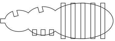
(1) Draw the body part and mortise and tenon structure of the bumblebee
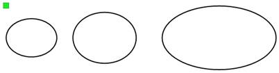
Use the Oval Tool to draw the body
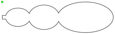
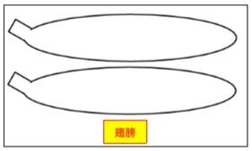
Click “Oval Tool”, move the mouse pointer to the blank area of the drawing area, hold down the left mouse button, drag the mouse to draw an oval. The width of the oval was changed to 20mm and the width of the oval was changed to 15mm for the head of the hornet. Similarly, draw an oval 25mm wide and 20mm high for the bumblebee’s chest; In addition, draw an oval with a width of 45mm and a height of 25mm as the abdomen of the bumblebee, as shown in the following figure.
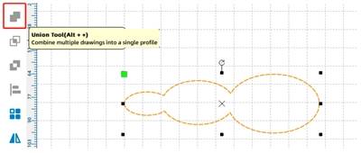
Use the Merge Tool to merge 3 ovals
Move the ellipses so that the ends of the three ellipses meet in turn. Select the three ovals and click the “Combine Tool” to merge the three ovals into one shape as the body part of the bumblebee, as shown in the following figure.
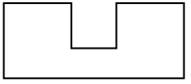
Use the Rectangle Tool to draw the tenon connecting the body to the face.
Click the “Rectangle Tool”, move the mouse pointer to the blank area of the drawing area, hold down the Ctrl key and the left mouse button at the same time, draw a square, and change its side length to 3mm. This square will be the tenon that connects the face. Use Align Guides to align it with the middle of the head in the body section. Select the square and body parts, click Merge Tool, and merge them to form a tenon, as shown in the following figure.
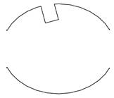
Use the “Rectangle Tool”, “Rotation” and “Difference Set Tool” to draw the connection between the head and the tenon
Click the Rectangle Tool and draw a rectangle with a width of 3mm and a height of 4mm. Move the mouse pointer to the toolbar, enter “-15” in the “Rotation” Angle input box, click “Rotation”, rotate it 15° counterclockwise, pull it to the middle position on the top of the bumblebee’s head, and click “Difference Set Tool” to form the sockets connecting the antennae and the head, as shown in the following figure.
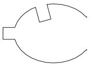
Use the “Rectangle Tool”, “Rotation” and “Difference Set Tool” to draw the sockets of the chest and wings
Click the Rectangle Tool to draw a rectangle with a width of 3mm and a height of 4mm. Move the mouse pointer to the toolbar, enter -15 in the Rotation Angle input box, click Rotate, and rotate the rectangle by 15° counterclockwise. Move it to the bumblebee chest and align it, click the Difference Set Tool to form the sockets that connect the chest to the wings, as shown in the following figure.
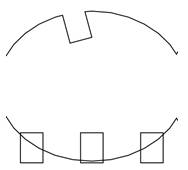
Use the Rectangle Tool and Rectangle Array to draw the tenon connecting the chest and legs
Click the “Rectangle Tool”, draw a rectangle with a width of 3mm and a height of 4mm, move it to the abdomen of the bumblebee, click “Rectangular Array”, enter 3 in the field of “number of levels”, 5 in the field of “horizontal spacing”, and 1 in the other fields to form the bases connecting the abdomen and legs, as shown in the following figure.
Use the Rectangle Tool and Rectangle Array to draw the bumblebee belly stripes.
Click “Rectangle Tool”, click the left mouse button, drag the mouse, draw a rectangle. Modify its width to 3mm and height to 25mm. Click “Rectangular Array”, and in the pop-up dialog box, enter 5 in the column of “Number of levels”, 4 in the column of “Horizontal spacing”, and 1 in the other columns, as shown in the following figure.
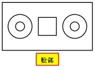
(2) Use the “Rectangle Tool” and “Oval Tool” to draw the bumblebee face.
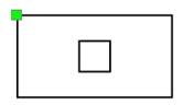
● Click the Rectangle Tool to draw a rectangle in the blank space of the drawing area. Modify the width of the rectangle to 15mm and the height to 8mm as the eye outline. Hold down the Ctrl key and the left mouse button to draw a square with a side length of 3mm, which is used as the mouth of the bumblebee white horse, and also the base connecting the face and head. Select the square and move it to the center of the rectangle, as shown in the following figure.
Move the mouse pointer to the gallery panel, select Concentric Circles from 1. Common Graphics under Select Gallery, and drag it to an empty space in the drawing area. Change the diameter of the outer circle to 4mm and the diameter of the inner circle to 1.5mm. Select the concentric circles and right-click to copy them as the two eyes of the bumblebee. Select the two concentric circles and move them to the left and right sides of the square, aligned with each other, as shown in the following figure.
(3) Draw bumblebee tentacles
Use the “Rectangle Tool” and “Difference Set Tool” to draw the tenon bases.
Click the Rectangle Tool and draw a rectangle with a width of 9mm and a height of 5mm and a square with a side length of 3mm. Select the square and align it to the bottom of the rectangle. Click the Difference Set Tool to delete the overlap, as shown in the following figure.
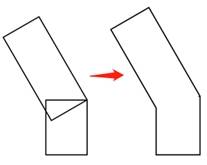
Use the “Rectangle Tool”, “Rotation” and “Union Tool” to draw the tenon
Click the Rectangle Tool to draw a rectangle with a width of 3mm and a height of 4mm 1; In addition, draw a rectangle with a width of 3mm and a height of 7mm 2, move the mouse pointer to the toolbar, enter “-30” in the Angle input box of “Rotate”, rotate 30° counterclockwise, and click “Rotate”. Move the rotated rectangle 2 to the right corner of rectangle 1, select the two rectangles at the same time, and click “Combine Tool” to merge them into one figure, as shown in the following figure.
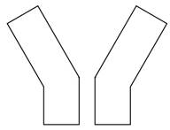
Select the merged graph, right-click, copy the same graph, and click “Flip horizontally” to flip it from left to right, as shown in the following figure.
Move the two antennae to the bases as shown in the following figure so that they are aligned with the left and right sides of the bases. Select all graphics and click “Combine Tools” to get the antenna with the bases.
(4) Draw the wings of the bumblebee
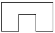
Use the “Rectangle Tool” and “Difference Set Tool” to draw the bases
Click the Rectangle Tool to draw a rectangle with a width of 12mm and a height of 5mm, and draw three squares with sides of 3mm. Move one square to the middle of the bottom of the rectangle, click the “Difference Set Tool”, and then move the other two squares to the left and right sides of the rectangle, as shown in the following figure, the wings can be completed.
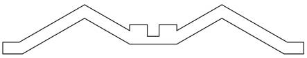
Use the “Ellipse Tool”, “Rectangle Tool” and “Union Tool” to draw wings
Click “Oval Tool” and draw an oval with a width of 45mm and a height of 10mm; Click the Rectangle Tool and draw a rectangle 3mm wide and 4mm high for the tenon. Move the mouse pointer to the toolbar, enter -60 in the Rotation Angle text box, and click Rotate to rotate the disk by 60° counterclockwise. Move it to the edge with the oval. Click the Merge Tool to merge the wings into a graph, as shown in the following figure.
(5) Draw the legs of the bumblebee
Use the “Rectangle Tool” and “Difference Set Tool” to draw the tenon.
Click the Rectangle Tool and draw a rectangle with a width of 12mm and a height of 5mm and a square with a side of 3mm. Move the square to the top of the rectangle and align it in the middle, click “Difference Set Tool” to process the difference set, and form a tenon, as shown in the following figure.
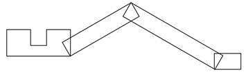
Use the “Rectangle Tool”, “Rotation”, “Horizontal Flip” and “Union Tool” to draw the legs of the bumblebee
Click the Rectangle Tool to draw a rectangle with a width of 15mm and a height of 3mm. Move the mouse pointer to the toolbar, enter -30 in the Rotation Angle input box, and click Rotate to rotate the rectangle by 30° counterclockwise. Align it with the lower right corner of the tenon (see the above figure); Click the Rectangle Tool to draw a rectangle 20mm wide and 3mm high, rotate it by 30°, and align it with the top right corner of the first rectangle; Draw another rectangle 5mm wide and 3mm high, aligned with the lower right corner of the second rectangle, as shown in the following figure.
Select the 3 rectangles, click the right mouse button to copy, click “horizontal flip”, and move the flipped graphics to the other side of the alignment. Select all graphics and click “Combine Tool” to merge them into a pair of legs, as shown in the following figure.
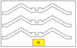
Click “Rectangular Array” and enter 3 in the “Vertical Number” field and 1 in the remaining fields to copy the other two pairs of legs of the bumblebee, as shown in the following figure.
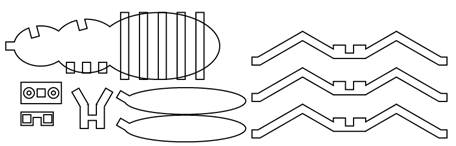
After completing the above steps, the bumblebee graph is drawn, as shown in the following figure.
Process pattern design
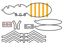
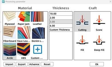
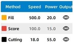
As shown in the following figure, select the stripe object on the abdomen of the bumblebee, set it as the “Yellow light carving” process layer, double-click the layer, and the “Processing parameters” dialog box will pop up. Set the processing material as acrylic sheet, the process as light carving, and the processing thickness as 0.1mm;
Select the bumblebee face object, set it as the “Red Tracing” process layer, double-click the layer, the “Processing parameters” dialog box will pop up, set the processing material to acrylic plate, the process to tracing line, and the processing thickness to 0.1mm;
Select the rest of the bumblebee, double-click the corresponding “Black cut” process layer, and the “Processing Parameters” dialog box will pop up. Set the processing material to acrylic plate, the process to cut, and the processing thickness to 3mm.
Finally, the layer sequence for adjusting the processing technology is: shallow carving → tracing → cutting, as shown in the following figure.
Thinking and debugging
(1) Observe and analyze whether the mortise and tenon connection modes of face and head, antenna and head, body and wings, and body and legs are the same? Can you design other mortise and tenon joints?
(2) Do the sizes of tenon and tenon need to be exactly the same? Modify the dimensions and experience the difference in fit tightness.
(3) If it is required that the joints of the 6 legs are also designed as mortise and tenon structures, is it OK? How to design?
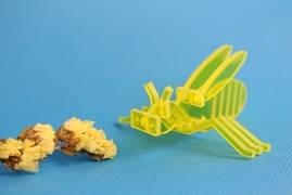
5.Display of finished products
The finished product is shown in the following figure.
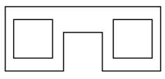
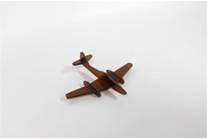
6.Extension exercise
Can you use LaserMaker to draw the mortise and tenon mouse shown in the following figure.
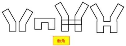
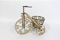
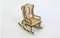
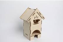
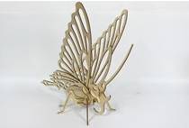
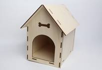
7.Work appreciation
The following figure is a variety of three-dimensional mortise and tenon structure works of LaserBlock open source community for your reference and appreciation.


.png "laser cutter Globle") International
International
 United States
 Brasil
 Canada
 Costa Rica
 Mexico
 Česká
Česká
 Romania
 Polska
 Ireland
 Portugal
 Lietuva
 Россия
 Deutschland
 Britain
 Україна
 France
 Sverige
 Italia
 Norway
 Denmark
 Ελλάδα
 한국
한국
 中国
中国
 中国香港
中国香港
 Israel
 中國臺灣
中國臺灣
 ジャパン
ジャパン India
India
 پاکستان
 پශ්රී ලංකා
 ประเทศไทย
 Australia
 New Zealand
 South Africa