Project Origins
The next item the designers are going to design is the carousel which is very popular among the tourists. The most important feature of the carousel is that the horse will follow the carousel to rotate. Players on the carousel can enjoy the music and the beautiful scenery of the playground.
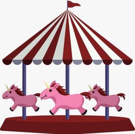
Determination of design options
Observational analysis
Carefully observe the carousel in the amusement park, found that the carousel’s most important feature is that it can be rotated and able to ride, so the design of this section focuses on the carousel structure and the wooden horse seat structure. Finally, a base is designed to hold the motor, and the motor provides power for the carousel to rotate.
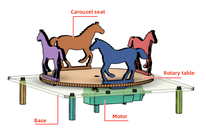
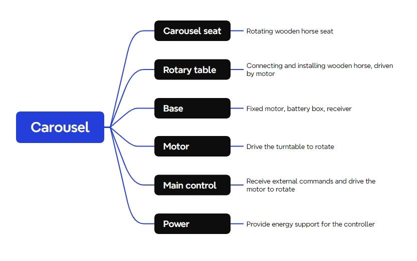
Through the above analysis, we can arrive at the main structure of the carousel: the wooden horse seat, the carousel and the base.
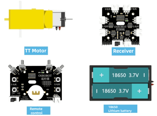
In the Laser Kingdom’s Maker Factory, there is a wealth of material kits for OSROBOT open source robots for little designers, so let’s go find these kits to make a carousel together.
Equipment List
The merry-go-round mainly involves the following equipment, this work of construction equipment list of a total of seven, see Table 2- 1
serial number | name (of a thing) | quantities |
1 | 2.4G remote control (with batteries) | 1 |
2 | 2.4G Receiver | 1 |
3 | TT motor (1:120) | 1 |
4 | 18650 Battery (with cable) | 1 |
5 | Basswood Laminate (40cm*60cm*3mm) | 1 |
6 | M3/M4 screws and nuts | 1 |
7 | 2.4G remote control (with batteries) | certain |
Structural design of the work
With the kit selected, we then began to design the structure of the carousel.
Creating a Parts List
First of all, according to the observation and analysis of the carousel and the parts in the equipment list, we can determine the structural parts table (Table 2- 2) that the work needs to be designed, and there are a total of 3 parts in the structural parts designed for this work.
part number | Part Name | part number | functionality |
1 | Trojan horse (constellation) | 4 | Carousel seat |
2 | rotary (traffic) | 1 | Connected to the installation of the Trojan horse, driven by the motor |
3 | foundation | 1 | Fixed motor, battery box, receiver |
laser modeling
After sorting out a clear parts list and following the list of parts list, we can start laser modeling.
We use mortise and tenon construction to secure the wooden horse to the turntable.
- Drawing the Trojan Horse
First of all, draw a horse-shaped seat, the beginning of the use of LaserMaker students, directly draw the shape of the horse is still difficult, we can first use the gallery to provide the “horse” graphics.
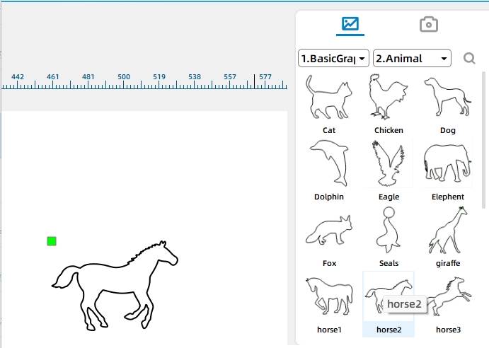
(1) in the Gallery [Animal Graphics] column, select the “Horse 2” graphics dragged to the drawing canvas area as a carousel seat,the result is shown in the following figure.
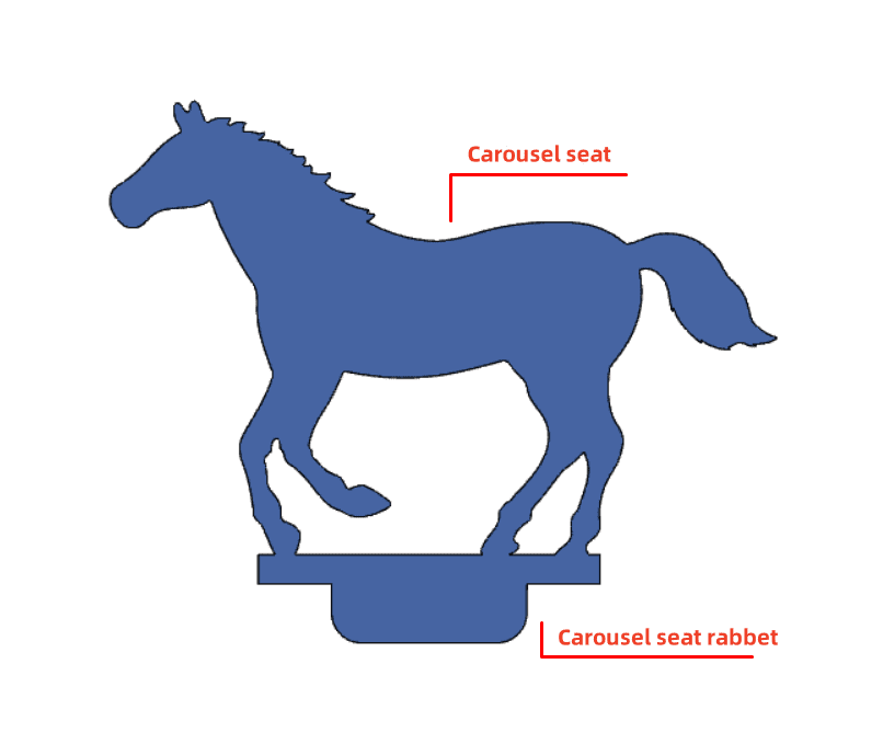
The “Horse 2” figure alone is not enough, a “wooden horse seat mortise and tenon” is also needed to combine with the “Horse 2” figure, in order to better integrate the wooden horse base with the turntable. The purpose of this is to better fit the base of the horse to the turntable. The wooden horse base with mortise and tenon can be inserted directly into the mortise of the turntable, and then it can be ridden. The effect of the “wooden horse base mortise and tenon” is shown in the following figure. It is made by combining two rectangles of different sizes.
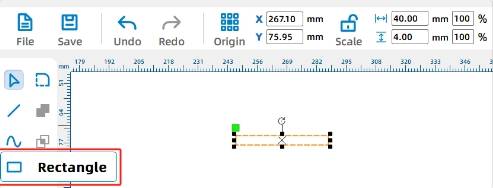
(2) the following drawing of the first rectangle of the wooden horse mortise and tenon, in the drawing toolbar, select [Rectangle Tool], the first rectangle drawn on the canvas, click the left button of the mouse to select one of the “rectangle” graphic, in the menu above the toolbar settings “width” for the 40mm, “high” for 4mm,is shown in the following figure.
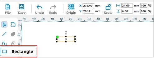
(3) using the same way to draw the second rectangle, as shown in the figure, in the drawing toolbar, select [Select Tool], left mouse button click to select the “Rectangle” graphics, set the “width” for 24mm, “height “for 6mm, in the following figure shown.
(4) Click the left mouse button drag function to center the two rectangles above horizontally.
Click the left mouse button, select any rectangle, long press the left button and move the selected rectangle and another rectangle alignment, alignment process will have a green alignment auxiliary line reference; the effect of the alignment is shown in the figure.
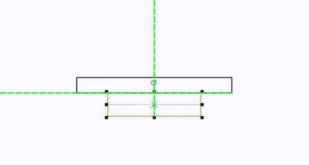
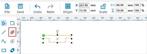
(5) the following two rectangles together, use the [Selection Tool] at the same time to select the two rectangles, and then click on the drawing toolbar in the [and set of tools] will be merged with the two rectangles, so that the “wooden horse seat mortise and tenon” on the drawing of a good,is shown in the following figure.
(6) “wooden horse seat mortise and tenon” design is complete, now the “wooden horse seat mortise and tenon” and “horse” graphics together. Use [Selection Tool] to select the “wooden horse mortise and tenon” and drag, and its “horse 2” part of the graphic overlap, as the following figure shown.
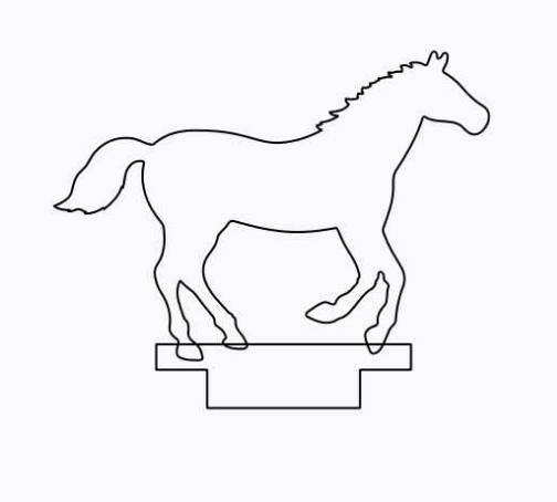
Observe the above figure can be seen graphic “horse 2” and “wooden horse seat tenon” graphic cross together, because the black line in the laser cutting machine default cut through, in the actual cutting of the two graphics will be cut off. So first of all need to cross the line segment for eraser processing, will be processed after the deletion of unwanted line segments can be.
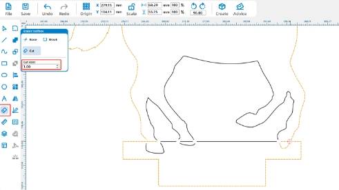
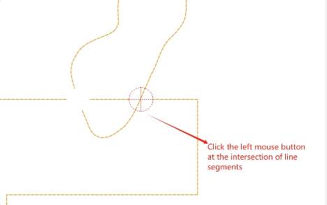
(7) in the drawing toolbar, select the [Eraser Tool], use the “Eraser” set to 1mm, in the overlap of the cross section of the line parts of the left mouse button can be erased off the line segment, the following figure shows.
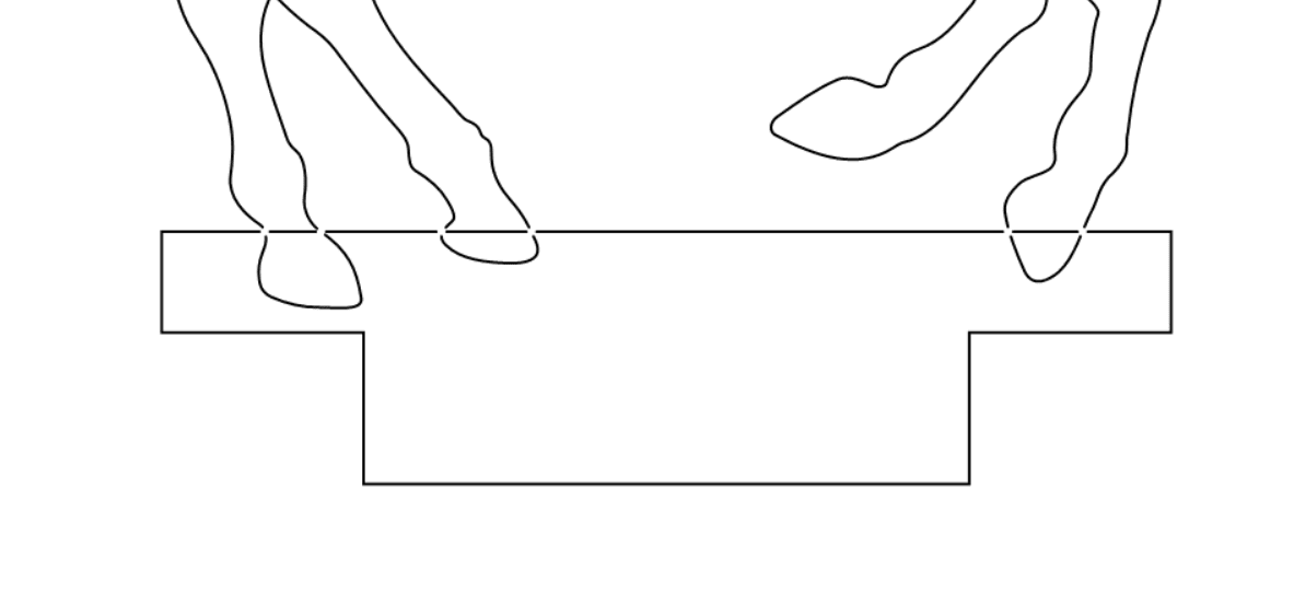
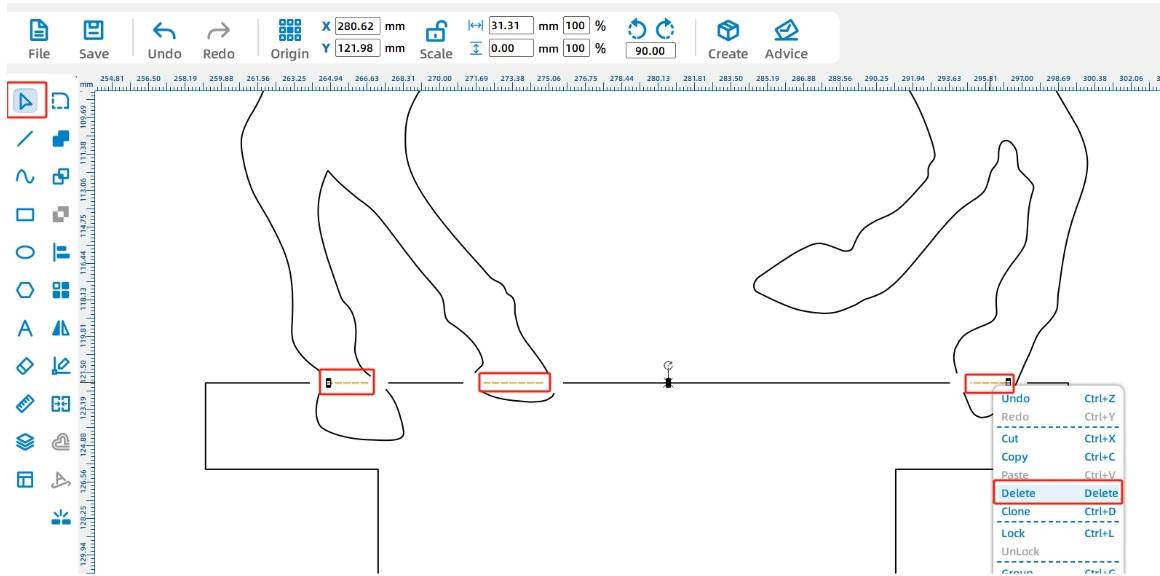
(8) then select these horizontal line segments, click the keyboard [Delete] key or click the right mouse button can be deleted, as the following figure shown.
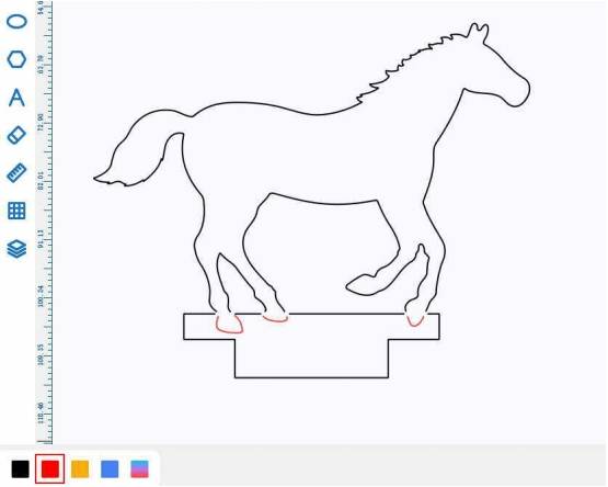
If you want to keep the “horseshoe” shape from being cut off, you need to set up a stroke (i.e., only the scratches will be retained during processing) for the horseshoe shape, which is represented by the red layer in the LaserMaker software.
(9) the use of [Selection Tool] were interrupted by the selection of horseshoe graphics, in the [Layer Settings] click on the red tracing layer, set to red tracing, as the following figure shown;
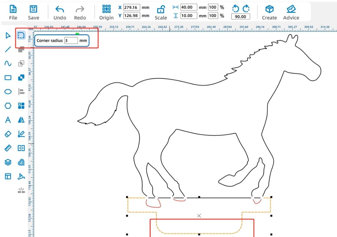
(10) In order to make it easier to insert the “wooden horse mortise and tenon” into the mortise of the turntable, it is necessary to round the corners of the “wooden horse mortise and tenon”.
Click on the drawing toolbar [Rounding Tool] radius set to 3mm, click on the bottom corner of the graphic for rounding settings, such as the following figure shown.
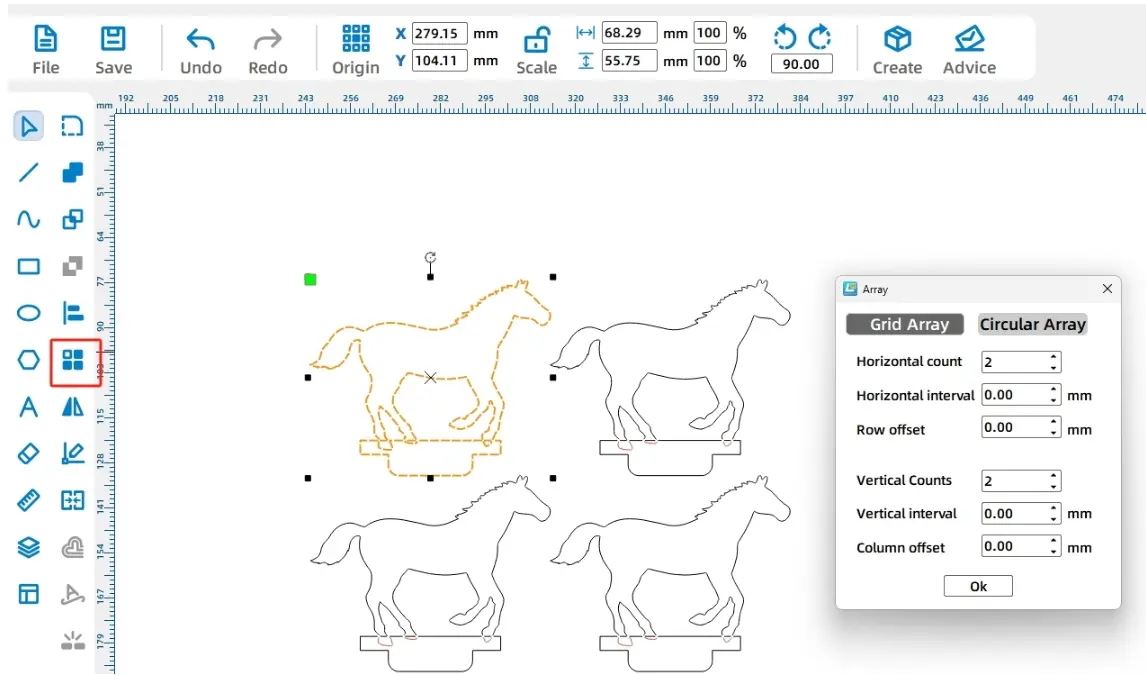
This carousel design requires the use of four wooden horse seats, in order to make a copy of the wooden horse seat of the graphic arrangement more neatly, here we use the [Rectangular Array] tool to reproduce.
(11) using the [Selection Tool] selected graphics, in the menu toolbar click on the [Rectangular Array] set the number of horizontal to 2, the number of vertical to 2; the following figure shown;
With the wooden horse seat design complete, the next thing to draw is the round carousel and the eyelets for the carousel that will be used to insert the wooden horse seat.
- Drawing a turntable
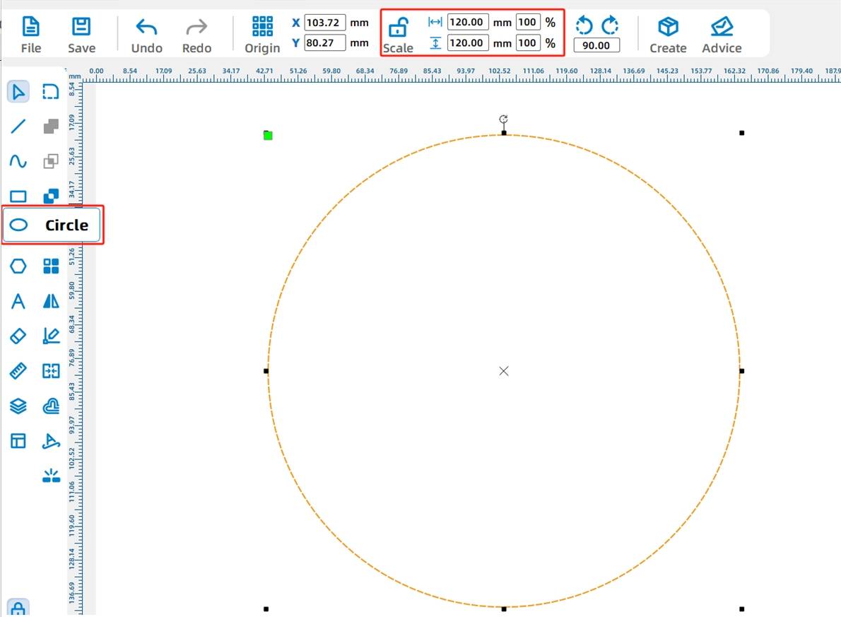
(1) First of all, in the Drawing Toolbar, select the [Ellipse Tool] in the canvas to draw an arbitrary size of the circle, and then in the menu toolbar [width and height tools], respectively, enter 100mm, you can get a diameter of 100mm of the circle. As the following figure shown.
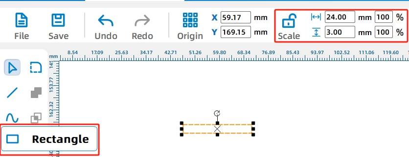
(2) Subsequently, the need to draw four mortise and tenon in the carousel used to insert the “wooden horse mortise and tenon”, first click on the [Rectangle Tool] to draw a rectangle, in the [Width and Height] dimensions of the size bar to set the width of 24mm, height 3mm can be obtained from a mortise and tenon, shown in the following figure.
Subsequently, the method of rectangular array approach was used to replicate multiple dauber eyes.
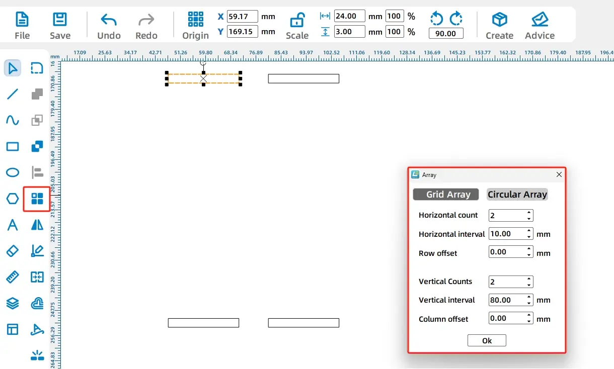
(3) selected rectangular eye, click [Rectangular Array Tool] set the number of horizontal 2, horizontal spacing of 10mm; water spaced rows shifted to 0; the number of vertical 2, the vertical spacing of 80mm, spaced column offset to 0; then you get the four identical eye, shown in the following figure.
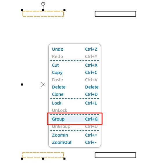
(4) Next, the need to adjust the location of the eye, we will be four eye placed in the carousel on the top, bottom, left, right, four directions, which will need to be four eye two groups of two groups, to facilitate the subsequent rotation and alignment of the operation. Use the [Selection Tool] to select one of the two eyelets, use the keyboard shortcut [Ctrl + G] or the right mouse button group function to group. After the same method will be used in another column of the eye for the group, as shown in the following figure.
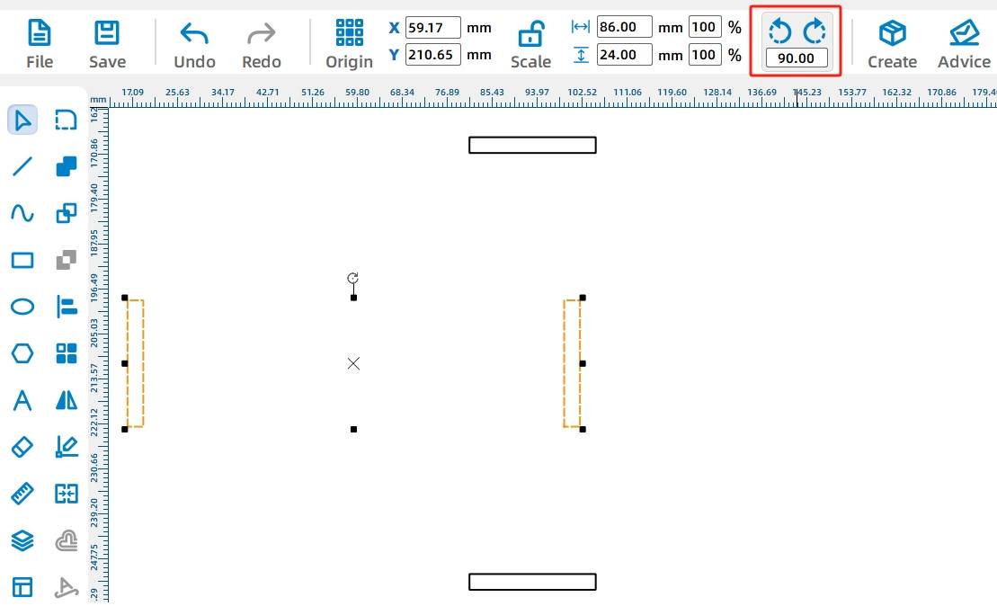
(5) Because the eyelets need to be evenly spaced horizontally and vertically, one column needs to be rotated 90 degrees and the horizontal eyelets and vertical eyelets need to be centered and aligned.
Use the [Selection Tool] to select the second column of the group after the eye, and then click on the graphic of the rotation button, set the “rotation angle of 90 °” to rotate. As the following figure shown.
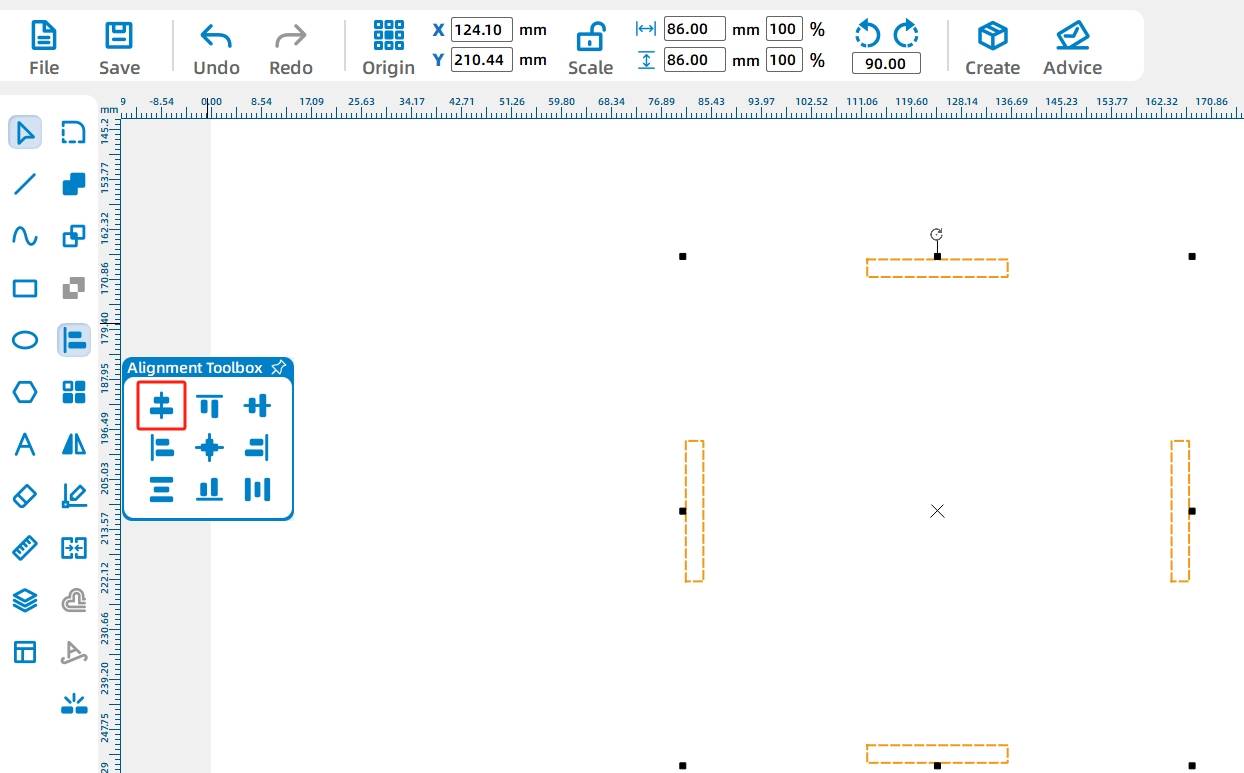
(6) Rotate all four selected eye, the use of alignment tools, respectively, the eye of the horizontal and vertical alignment of the center, alignment of the eye, as shown in the following figure.
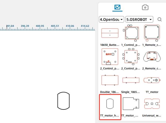
(7) Next, you need to add the TT motor hole in the carousel, in the Gallery [Open Source Robotics Hardware], select “TT motor hole” dragged into the canvas, as shown in the following figure.
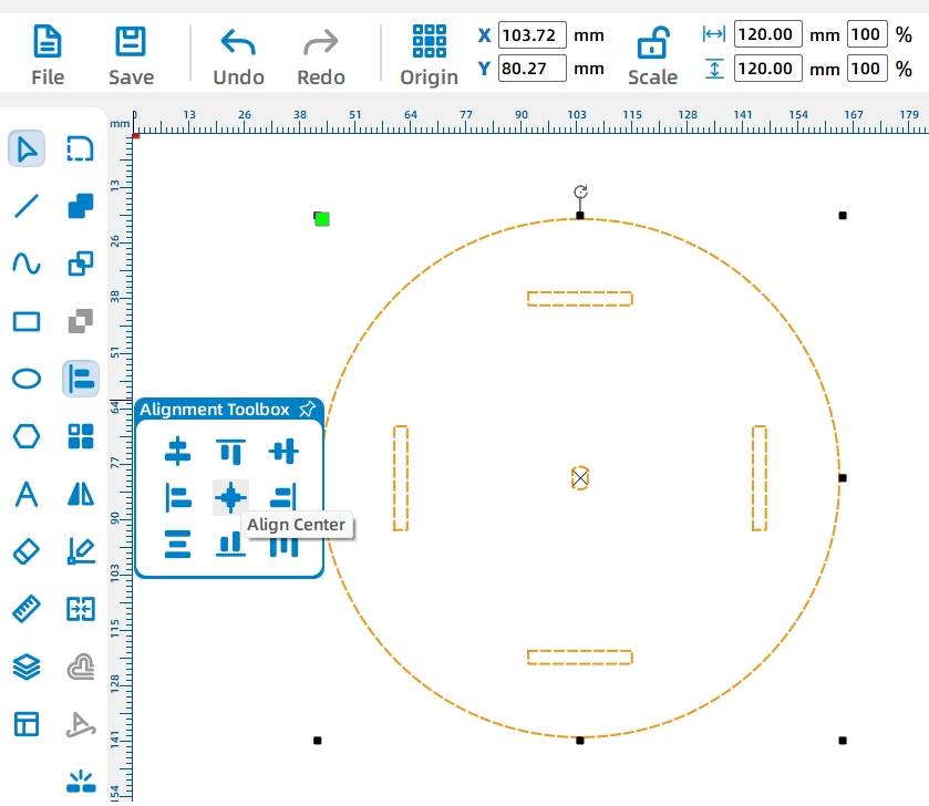
(8) the use of [Selection Tool] will be a circle graphic, TT hole graphics, four eye rectangle all selected, click on the [Alignment Toolbox] in the horizontal center alignment and vertical center alignment tool, so that the carousel carousel on the drawing is complete, as shown in the following figure.
Next, draw the base, in which the parts such as the motor, OSROBOT receiver and battery need to be fixed.
This involves determining where the various parts are located in the turntable. First we draw a square base, then we draw the same circle in the base as the turntable as a reference mark, and then we draw a small circle as a reference mark for the TT motor graphic.
- Drawing the base
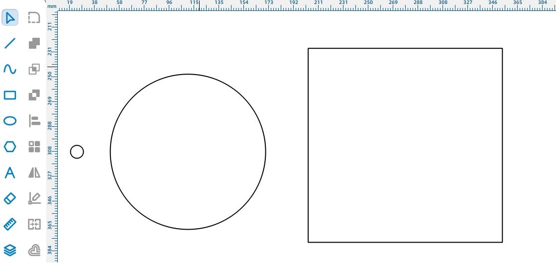
(1) in the Drawing Toolbar, select [Rectangle Tool] in the canvas were drawn 10mm in diameter, 120mm circle, side length of 150mm square, as shown in the following figure.
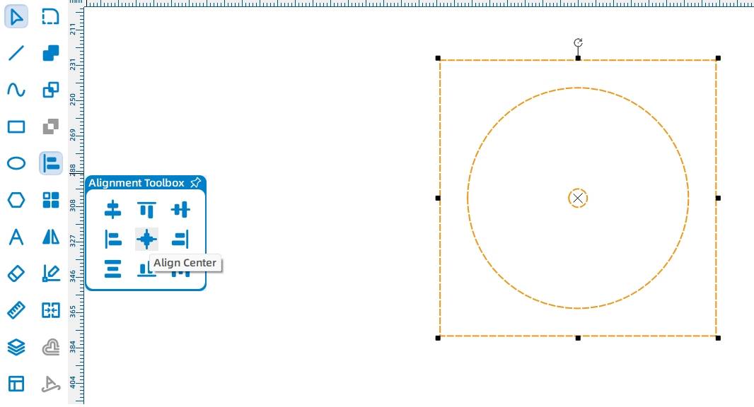
(2) the use of [Selection Tools] will be 10mm in diameter, 120mm circle, side length of 150mm square all selected, click [Alignment Toolbox] in the horizontal center alignment tool and vertical center alignment tool will be centered on the two circles and squares, as shown in the following figure.
In order to round the four corners of the base, it is necessary to set the rounding of the four corners.
(3) Select the 150mm * 150mm rectangle drawn in the drawing toolbar, select [Rounded Corner Setting Tool], set the radius of the rounded parameters for 20mm, and then click on the four right angles can be modified to rounded corners, as shown in the following figure.
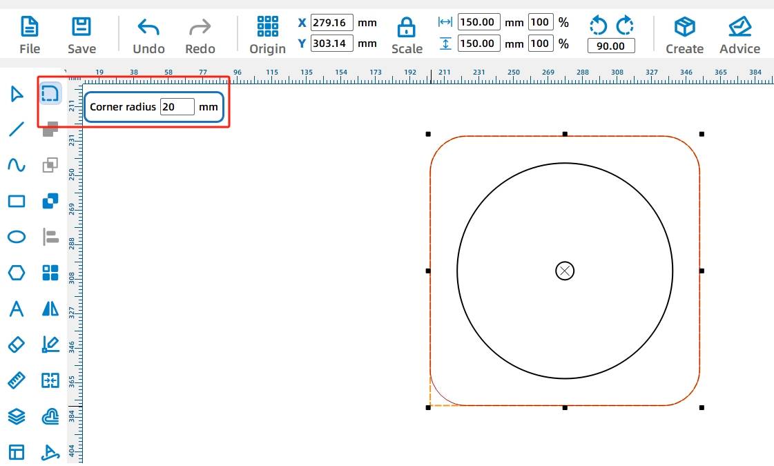
The base contour is complete, now the TT motor graphics need to be placed in the base
(4) in the gallery [Open Source Robotics] in the selection of “OSROBOT motor” dragged into the canvas and group, the TT motor graphic in the circular hole and the center of the base of the circular hole overlap, and delete the redundant circle, so as to determine the TT motor fixed holes, as shown in the following figure.
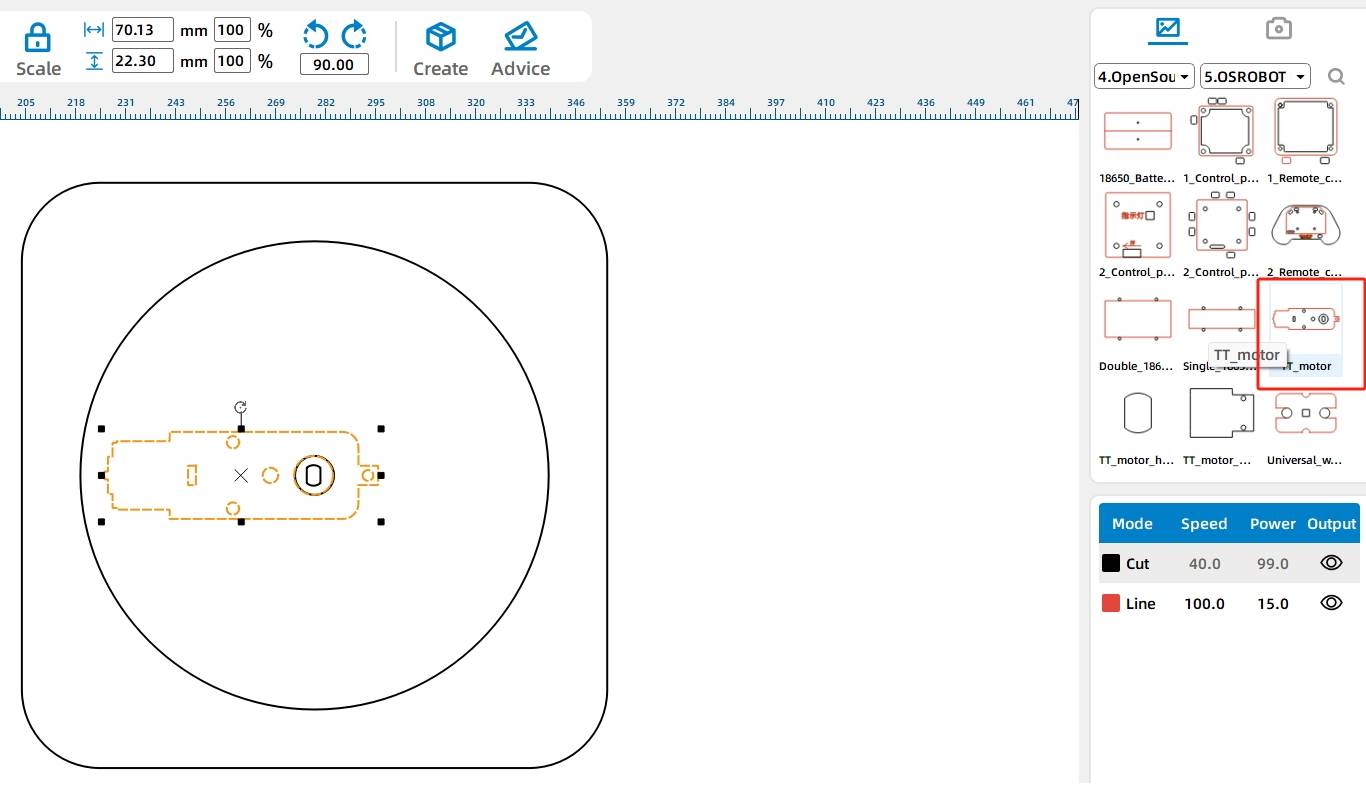
Next, locate the control board and battery box mounts in the base
(5) In the Gallery [Open Source Robotics Hardware], select the 2.0 control board external, drag it into the canvas to delete the small rectangular holes around it, select the rotate button in the control board graphic, and set the rotation angle to “-90°”. As shown in the following figure.
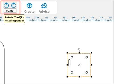
(6) 18650 battery box and drag it into the canvas, placing the two graphics above and below the TT motor graphic, as shown in the following figure.
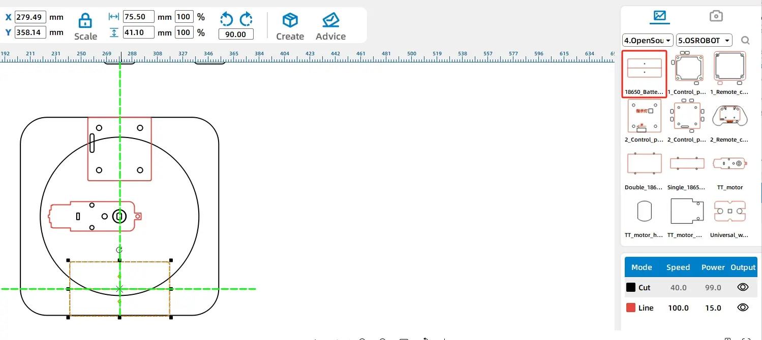
(7) Because the black line segment is the default cutting process in LaserMaker software, you need to set the large circle used as a position reference to the red traced line process.
Use the [Selection Tool] to select the circle with a diameter of 120mm, click on the red layer in the [Layer Toolbar] to set the selected circle as a tracing line, as shown in the following figure.
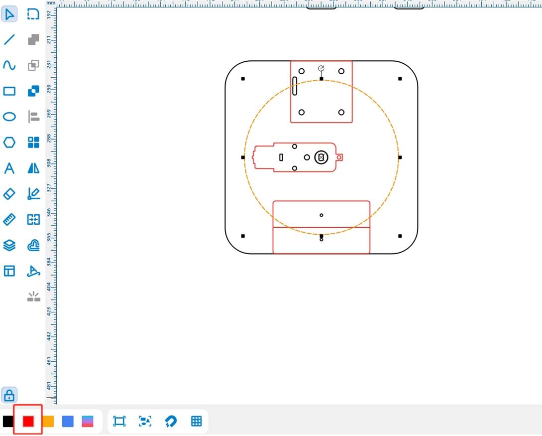
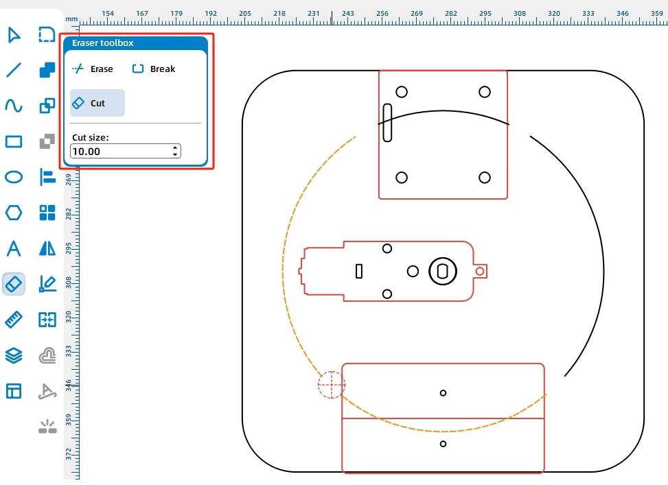
(8) the lines in the figure above have part of the cross overlap, for the sake of aesthetics, you can delete some of the lines. The use of [Eraser Tool] in the erase line function, in the graphic intersection parts to interrupt and delete, as shown in the following figure.
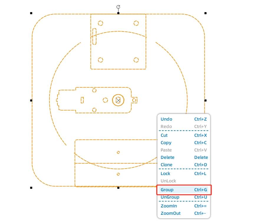
(9) The base design is complete, you can group the graphics on the base. The use of [Selection Tool] all selected graphics in the canvas, use the keyboard shortcut [Ctrl + G] or the right mouse button group function to group. As shown in the following figure.
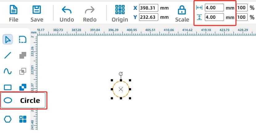
(10) After that, in order to facilitate the installation of nylon support columns in the base, you need to draw screw holes for the base. Use the [Oval Tool] to draw a diameter of 4MM square circle, shown in the following figure.
(11) then use the Rectangular Array Tool array out of 4 round holes, select the 4MM square circle, click [Rectangular Array Tool] horizontal number of 2, the horizontal spacing of 120; offset to 0; the number of vertical 2, the vertical spacing of 120, offset to 0; as shown in the following figure.
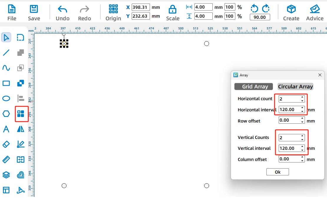
(12) After that, group the 4 holes. Use the [Selection Tool] to select all the graphics in the canvas, use the keyboard shortcut [Ctrl + G] or the right mouse button group function to group. As shown in the following figure.
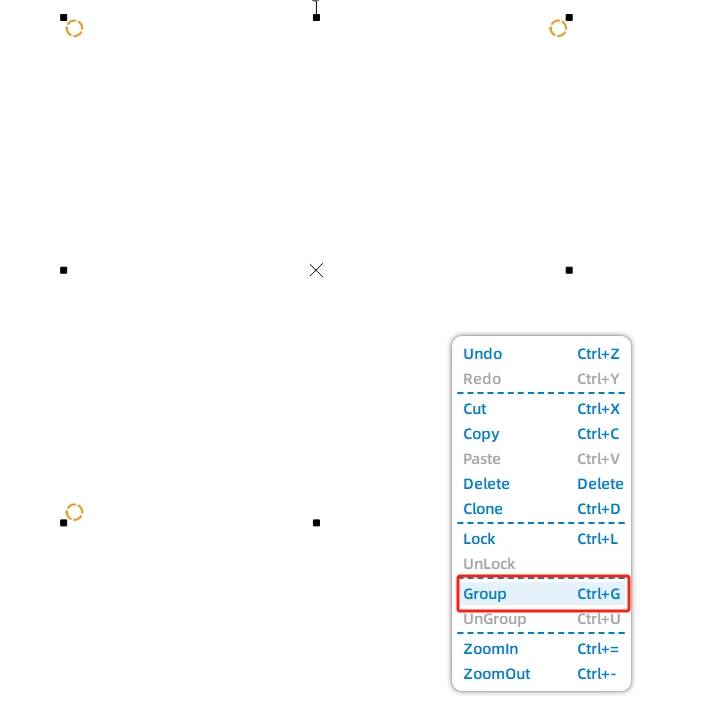
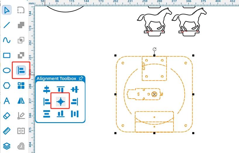
(13) group after the fixed hole can be centered with the base of the alignment, the use of [Selection Tools] all selected graphics in the canvas, in the [Alignment Toolbox] in the use of horizontal center alignment, vertical center alignment, will be aligned with all the graphics. As shown in the following figure.
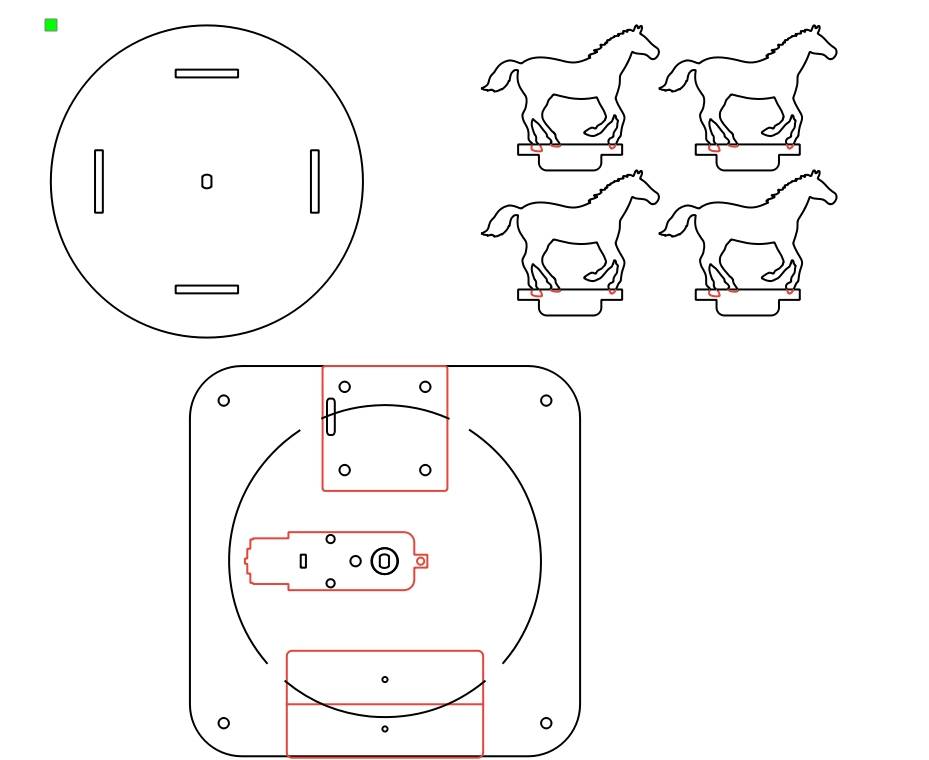
This way the carousel design drawing is all complete, and the final layout of the completed drawing is shown in the following figure.
laser processing
Once the drawing is designed, we set up the process to cut.
1.Setting parameters
(1) Tracing
Double-click the red block in the machining process area, select 1. basswood plywood for the material of the machining parameters, select tracing for the machining process, select 0.10 for the machining thickness, and click OK.
(2) Cutting
Double-click the black block in the Machining Process area, select 1. basswood plywood for Material for Machining Parameters, select Cutting for Machining Process, select 3.00 for Machining Thickness, and click OK.
- Start building things
Turn on the power switch of the laser cutting machine, turn on the laser switch, wait for the start building button to turn blue, click start building, wait for the drawing to be uploaded to the laser cutting machine, click the start button of the laser cutting machine panel to start cutting.
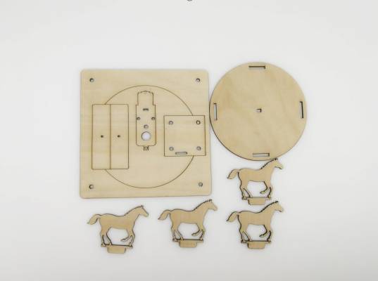
Assembled Models
After getting the finished parts, we can now enter the model assembly, first look at the circuit wiring, as shown in the following figure.
Circuit Wiring
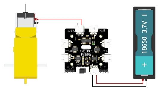
Next, structural assembly
Structural assembly
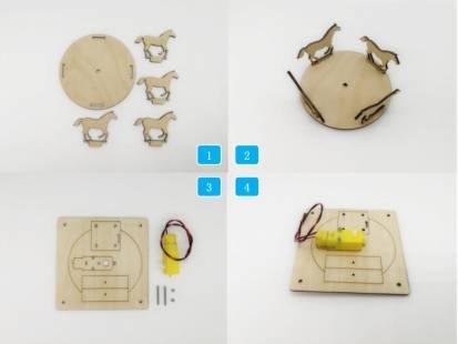
Step 1: Identify 4 Trojan Seats and 1 Turntable
Step 2: Insert the 4 Trojan horses into the eyelets of the carousel.
Step 3: Locate the base, 1 TT motor and the M3 screws and nuts holding the motor in place
Step 4: Secure the TT motor to the bracket using M3 screws and nuts. As shown in the following figure.
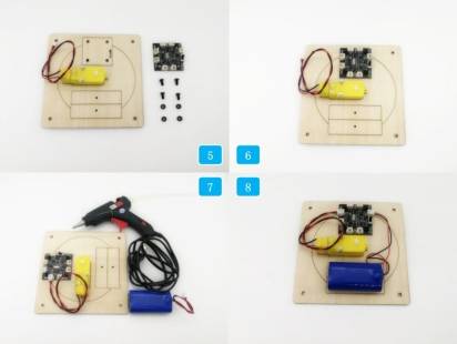
Step 5: Install the receiver on top of step 4, locate the 4 M4 screw nuts and the receiver
Step 6: Secure the receiver to the base using M4 screw nuts
Step 7: Install 18650 battery on top of step 6
Step 8: Use a glue gun to attach the battery to the bracket and connect the motor, battery and receiver. Refer to the following figure Circuit Wiring Diagram for wiring method.
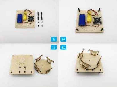
Step 9: Find 4 M4 short screws, 4 M4 nylon posts
Step 10: Fix the M4 screws and M4 nylon posts on the back of the base.
Step 11: Locate the carousel with the Trojan horse installed in step 2
Step 12: Install the carousel with the Trojan horse seat on the TT motor shaft so that the carousel is installed, as shown in the following figure.
summarize
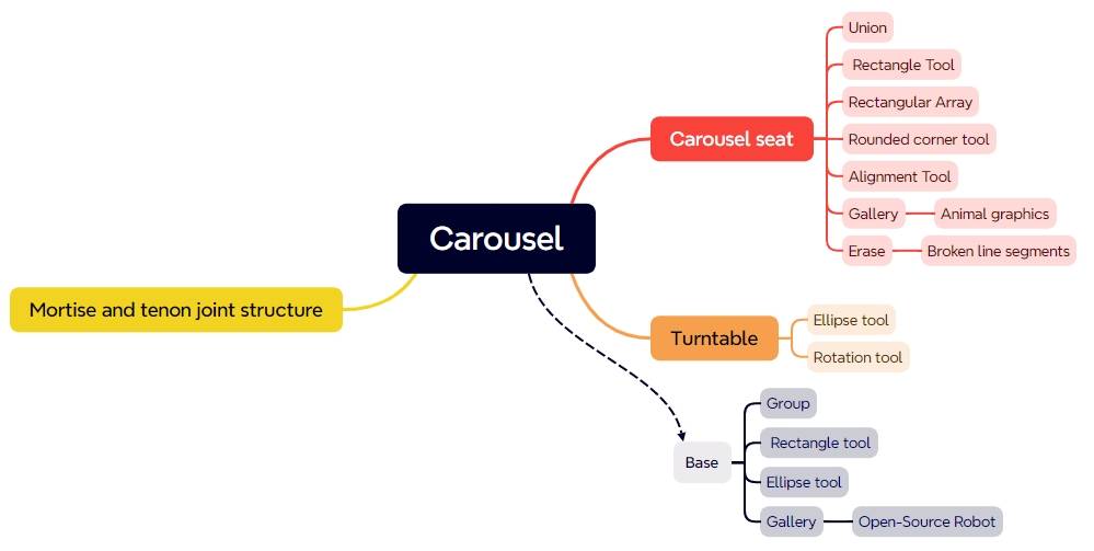
The carousel was successfully created with the careful design of the young designers. Review in this design, learning to use the LaserMaker in the selection, circle, rectangle, eraser, alignment, rectangle array, layer cut, stroke, text, eraser, rounded corners and other drawing tools, as shown in the following figure.
The designers successfully designed a wonderful and exciting carousel rides, so that the children have fun, I heard that the next session of the designers in the preparation of a wonderful visual feast for everyone to let, we find out.
Thinking Outside the Box
In this section of the design process, the “tenon of the wooden horse seat” intersects with the graphic of the “horse” seat, and its line segment processing requires some effort to carefully remove, and if you are not careful, you will lose a hoof. Is there any way to improve this situation? Let’s think about it together.
Browse Thunder Laser
Bolt >



.png) International
International
 United States
 Brasil
 Canada
 Costa Rica
 Česká
Česká
 Ελλάδα
 Polska
 Ireland
 Portugal
 Lietuva
 Россия
 Deutschland
 Britain
 Україна
 France
 Sverige
 Italia
 Norway
 Denmark
 Romania
 한국
한국
 中国
中国
 ประเทศไทย
 中国香港
中国香港
 Israel
 中國臺灣
中國臺灣
 India
India
 پاکستان
 پශ්රී ලංකා
 ジャパン
ジャパン
 Australia
 New Zealand
 South Africa