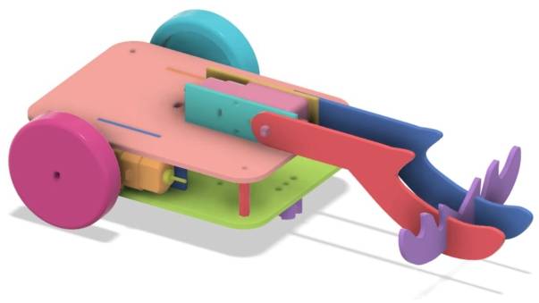
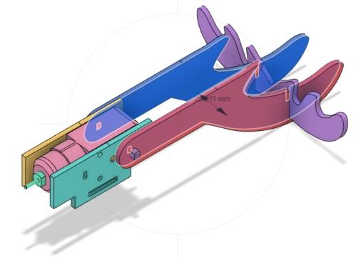
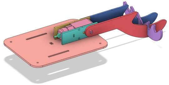
With the unwavering efforts of our designers, the basic chassis design has been completed. Next, we embark on a new challenge: designing a collector car for Planet M to aid players in gathering energy stones.
Design Proposal
Analyzing the Task
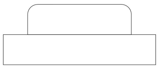
Energy stones are hollow, interlocking cubes. We propose designing a hook mounted on a TT motor, which rotates to latch onto the stones, fulfilling the collection task. For aesthetic purposes, we’ll shape the hook like a deer’s antler, which we’ll refer to as “deer’s antler” in the following.
Utilizing the pre-designed chassis, we’ll focus on the energy stone collection mechanism. Given the TT motor as the power source, we’ll design a bracket to mount the motor securely on the chassis. Then, we’ll create the antler-shaped hook. To prevent the stones from sliding off and ensure stability, we’ll design two vertical antlers and one horizontal one, interlocking with a finger joint.
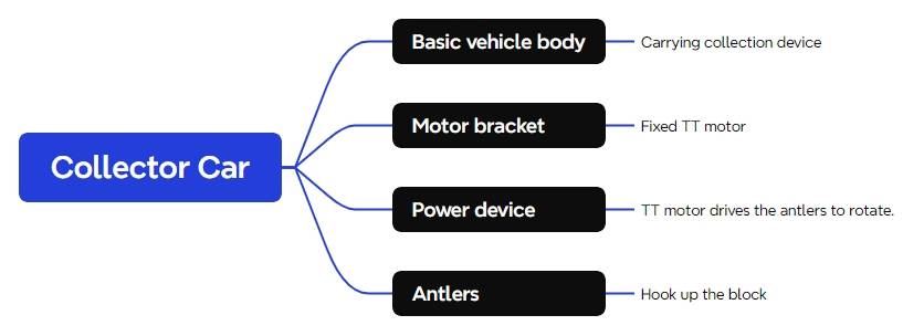
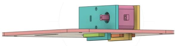
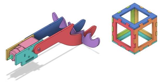
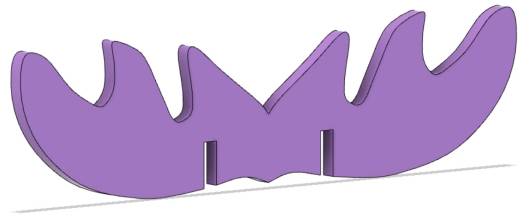
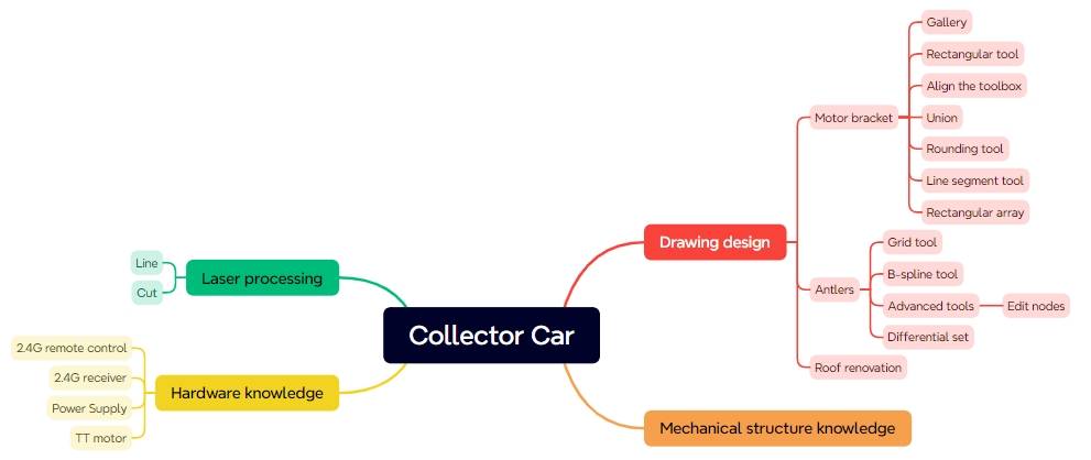
In summary, the collector car comprises four main components: the base chassis, motor bracket, power unit, and antlers, as illustrated below.
Materials List
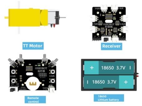
With the basic components of the collector car planned, we can choose appropriate materials for design, processing, and assembly to achieve the intended functionality. The base chassis, already designed in the previous project, requires minimal changes, such as adding mortises for the motor brackets and wiring holes on the top plate. Basswood plywood can be used for both the motor brackets and antler shapes. The TT motor’s gear ratio can be selected based on individual preferences, with faster operators preferring lower ratios and slower operators preferring higher ratios. Therefore, the final materials list is as follows:
No.
Item
Quantity
1
Base Chassis
1
2
TT Motor
1
3
Basswood Plywood (40cm60cm3mm)
1
Structural Design of the Project
Having confirmed the deer antler design for the collection mechanism of the collector car, we can proceed with the structural design based on our previous analysis.
Creating a Parts List
Based on the functional requirements of the collector car and the materials list, we can determine the parts list for this project. The structural components of this design consist of four main parts.
Part No.
Part Name
Quantity
Function
1
Base Chassis
1
Carrying the collection mechanism
2
Motor Bracket
1
Securing the TT motor
3
Power Unit
1
Driving the rotation of the deer antler
4
Deer Antler
1
Hooking onto the energy stones
Laser Modeling
With the parts list as a guide, we can officially enter the design phase and start laser modeling.
Drawing the Motor Bracket
The collector car’s collection mechanism utilizes a TT motor as its power source, so our first task is to design a bracket for the TT motor.
(1) Determine the dimensions of the motor bracket.
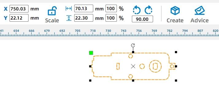
Open the LaserMaker software and from the “Open-Source Robotics” option in the LaserMaker library, select the “TT Motor” graphic and drag it onto the canvas. Right-click on the motor graphic and select the grouping function to combine all the motor’s components. Check the dimensions of the TT motor, which are 70.13mm wide and 22.30mm tall. Based on these measurements, the dimensions of the motor bracket can be set as 72mm wide and 22.30mm tall to account for any additional clearance or mounting requirements.
(2) Drawing the Main Body of the Motor Bracket
Using the Rectangle Tool from the Drawing Toolbox, draw a rectangle on the canvas with a width of 72mm and a height of 22.30mm to serve as the main body of the motor bracket. Utilize the Alignment Tools from the Drawing Toolbox, specifically the “Horizontal Center Alignment” and “Vertical Center Alignment” tools, to align the TT motor graphic with the rectangular motor bracket body.
(3) Designing the Mortise and Tenon Joints for the Motor Bracket
To securely attach the motor bracket to the base chassis, we can extend the tenon (male joint) of the motor bracket and add a mortise (female joint) to it. This mortise-and-tenon joint, along with a through-tenon, will firmly lock the motor bracket in place on the chassis.
Using the Rectangle Tool from the Drawing Toolbox, draw a rectangle on the canvas with a width of 40mm and a height of 9mm to serve as the tenon of the motor bracket. Drag this rectangle to align its top edge with the bottom of the motor bracket’s main body and vertically center it.
(4) Using the Rectangle Tool from the Drawing Toolbox, draw a rectangle on the canvas with a width of 20mm and a height of 3mm to serve as the mortise for the through-tenon. Ensure that this rectangle is horizontally and vertically centered within the tenon of the motor bracket using the “Horizontal Center Alignment” and “Vertical Center Alignment” tools from the Alignment Tools in the Drawing Toolbox.
(5) Combining the Motor Bracket Main Body and the Tenon to Form the Final Motor Bracket
Holding down the Ctrl key, select both the motor bracket main body and the motor bracket tenon. Then, use the Union tool from the Drawing Toolbox to merge the two parts, forming the initial shape of the motor bracket.
To improve cutting aesthetics and efficiency, we’ll keep only essential holes. Right-click to ungroup the TT motor, delete redundant outlines, holes, and circles. Duplicate the bracket for a total of two pieces.
(6) Drawing the Pin to Secure the Motor Bracket
In the previous step, we used a through-tenon to secure the motor bracket, with the mortise already prepared. Next, we need to draw a pin that can latch onto the motor bracket.
To ensure the pin secures the motor bracket firmly, the tenon head must be slightly larger than the mortise gear. Considering factors like laser compensation, we can set the tenon width to 20.4mm.
Using the ‘Rectangle Tool’ in the ‘Drawing Toolbox’, draw a rectangle with a width of 20.4mm and a height of 6mm for the tenon head. Additionally, draw a rectangle with a width of 30mm and a height of 6mm for the pin handle, aligning its top edge with the bottom edge of the tenon head and centering them horizontally.
To make the pin easier to insert into the mortise, we can use the ‘Rounded Corner Tool’ in the ‘Drawing Toolbox’ to apply a rounded corner with a radius of 2mm to the tenon head.
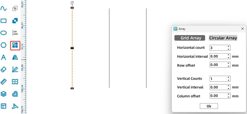
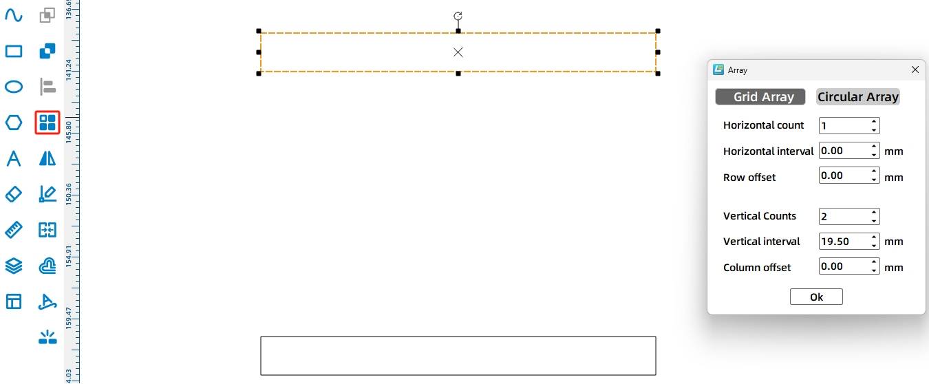
To prevent the tenon head from being too tight, we can create slits on it. Using the ‘Line Tool’ in the ‘Drawing Toolbox’, hold Ctrl and draw a vertical line 6mm tall. Apply a rectangular array with 3 horizontal lines, 8mm spacing, and no offset. Group the three lines together by right-clicking and selecting the grouping function.
Select the three vertical lines, drag them to the position of the tenon head, and align them horizontally and vertically. Holding Ctrl, select the tenon head and handle, then use the ‘Union’ tool in the ‘Drawing Toolbox’ to merge them into the final pin. Since there are two motor brackets, we need two pins. Drag the mouse left button to select the pin and duplicate it.
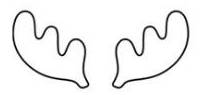
2. Drawing the Antler Hook
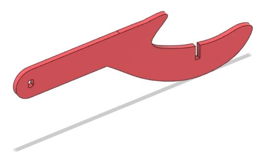
The antler-shaped hook can easily hook the energy stone, both aesthetic and practical.
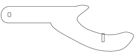
(1) Drawing the Forward-Facing Antler
The forward-facing antler is a crucial component for hooking the energy stone. It consists mainly of a handle with a TT hole and a hand-shaped antler. Let’s go through the steps of drawing it.
Click on the ‘Grid Tool’ in the ‘Drawing Toolbox’ to aid in the upcoming drawing.
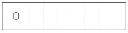
Using the ‘Rectangle Tool’ in the ‘Drawing Toolbox’, draw a rectangle on the canvas with a width of 90mm and a height of 20mm. From the ‘Open-Source Robot’ section of the LaserMaker gallery, select the ‘TT Motor Hole’ graphic and drag it to the left side of the rectangle, aligning it vertically to form the handle of the forward-facing antler.
Next, we need to draw the hand-shaped antler, which requires using curves. The ‘B-Spline Tool’ in Lasermaker allows us to draw Bézier curves.
Tips:
Bézier curves, also known as Bezier curves or Bezier splines, are mathematical curves used in 2D graphics applications. Vector graphics software commonly employs them to precisely draw curves. Bézier curves are composed of segments and nodes, where nodes are draggable points and segments resemble elastic rubber bands. The pen tool seen in many drawing software tools is used to create such vector curves. Bézier curves are crucial parametric curves in computer graphics and are also available in some mature bitmap software, such as PhotoShop.
Click on the ‘B-Spline Tool’ in the ‘Drawing Toolbox’ and determine each node of the curve by clicking the left mouse button once on the canvas until the approximate hand shape is drawn, ultimately forming a closed curve.
However, the hand-shaped curve we just drew is not perfect. We still need to adjust it. Click on ‘Advanced Tools’ in the ‘Drawing Toolbox’ and select ‘Edit Nodes’. Adjust the position of nodes and the tangents (both angle and length can be modified) to make the curve smoother.
Click the ‘Grid Tool’ in the ‘Drawing Toolbox’ and turn it off. Click the ‘Selection Tool’ in the ‘Drawing Toolbox’, hold down the Ctrl key to select the rectangle and the hand-shaped curve, use the ‘Union’ tool in the ‘Drawing Toolbox’ to merge the two, and apply the ‘Rounding Tool’ with a rounding radius of 10mm to round off the two right angles on the left side (to prevent the positive antler from hitting the base chassis when rotating), thus forming the positive antler.
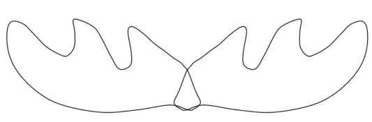
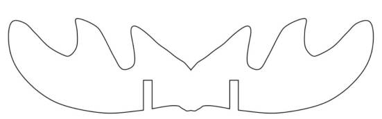
(2) Drawing the Horizontal Antler
While the forward-facing antler can already hook the energy stone, its connection to the TT motor shaft does not guarantee structural stability. Additionally, after hooking the stone, rotating the antler can cause the stone to get stuck and be difficult to remove. Therefore, inserting a horizontal antler between the two forward-facing antlers not only enhances stability and aesthetics but also prevents the energy stone from falling towards the motor during rotation, while still retaining its ability to hook the stone.
We can search online for our favorite antler shapes to use as references for drawing our own horizontal antler design.
Using the B-Spline Tool in the Drawing Toolbox, click the left mouse button once on the canvas to determine each node of the curve until an approximate shape of an antler is drawn. Then, utilizing the “Edit Nodes” function of the Advanced Tools in the Drawing Toolbox, adjust the positions and tangents of the nodes to make the antler appear smoother and more realistic. Select the antler and set its dimensions to a width of 64mm and a height of 31mm.
Select the drawn antler, right-click to duplicate it, drag the duplicate to horizontally align it with the original, and combine them to form the shape of the horizontal antler.
Select both antlers and use the Union tool from the Drawing Toolbox to merge them into a single shape.
(3) Drawing the Cross Tenon
To further stabilize the antler structure, a cross tenon can be inserted to secure the forward-facing antlers to the horizontal antler.
Using the Rectangle Tool in the Drawing Toolbox, draw a rectangle on the canvas with a width of 2.85mm and a height of 10mm as the mortise. Considering laser compensation, a width of 2.85mm is chosen for easier securement.
Select the rectangle and utilize the Array tool in the Drawing Toolbox, specifically the rectangular array option, with horizontal count set to 2, horizontal spacing at 25.5mm, and no offset between rows. Click to confirm and create the mortises for the horizontal antler.
Select the two rectangles, drag them to suitable positions on the horizontal antler, and align them vertically and centrally. Select one of the rectangles and use the Difference Tool in the Drawing Toolbox to create a mortise. Repeat the same operation with the other rectangle to form the second mortise. This completes the final design of the horizontal antler with mortises.
Draw a rectangle with a width of 2.85mm and a height of 10mm using the Rectangle Tool in the Drawing Toolbox, and drag it to a suitable position on the forward-facing antler.
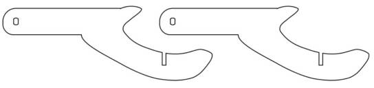
Select the rectangle and use the Subtraction Tool in the Drawing Toolbox to create the mortise. This completes the drawing of one forward-facing antler. Select the antler, right-click to duplicate, and finish the drawing of the final two forward-facing antlers.
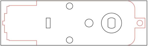
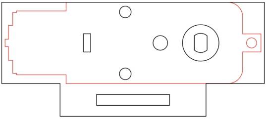
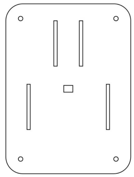
3. Modifying the Base Vehicle Roof Panel
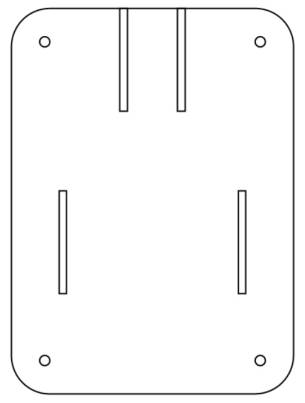
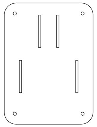
The motor bracket will ultimately be attached to the base vehicle, therefore, we need to add mortises for the motor bracket on the roof panel of the base vehicle.
(1) Draw the mortise for the motor bracket
In the first step, draw the tenon of the motor bracket with dimensions of 40mm wide and 9mm high. Since the thickness of the basswood laminate in the workshop is 3mm, the mortise dimensions can be set as 40mm wide and 3mm high. Use the “Rectangle Tool” in the “Drawing Box” to draw a rectangle with dimensions of 40mm wide and 3mm high on the canvas. As the thickness of the TT motor is 19.5mm, select this rectangle and use the “Array” tool in the “Drawing Box” to create a rectangular array with 2 vertical rows, horizontal spacing of 19.5mm, and staggered offset of 0. Click “OK” to form the mortise for the motor bracket.
(2) Determining the Position of the Mortise for the Motor Bracket
Select the two rectangles serving as the mortise for the motor bracket, rotate them 90°, and drag them to align with the upper edge of the base car body roof panel, ensuring vertical centering alignment.
Select the mortise for the motor bracket and increase its Y-coordinate by 15mm to move it downward by 15mm, marking its final position.
(3) Drawing the Wiring Hole
Since the TT motor with a rotating horn is positioned above the base chassis, to facilitate the connection of the motor to the OSROBOT control board, we need to reserve a wiring hole on the top panel of the base chassis.
Use the “Rectangle Tool” in the “Drawing Box” to draw a rectangle with dimensions of 8mm wide and 6mm high on the canvas. Drag and drop it to the center of the top panel, aligning it horizontally and vertically in the center.
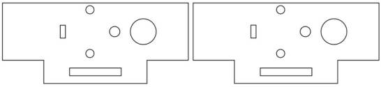
4.Layout
Laser Processing
After the drawing design is completed, we can proceed with cutting by setting the processing parameters.
Set Parameters
(1) Outlining
Double-click the red block in the processing parameter area. Select Basswood Plywood for the material, Outlining for the processing technique, and 0.10 for the cutting depth. Click “OK”.
(2) Cutting
Double-click the black block in the processing parameter area. Select Basswood Plywood for the material, Cutting for the processing technique, and 3.00 for the cutting depth. Click “OK”.
Start Manufacturing
Turn on the power switch of the laser cutting machine and the laser switch. Wait for the “Start Manufacturing” button to turn blue, then click it. Once the drawing is uploaded to the laser cutting machine, press the start button on the laser cutting machine panel to begin cutting.
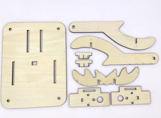
Assembly of the Model
Here is the actual image of the cutout obtained after the fabrication process in the workshop:
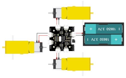
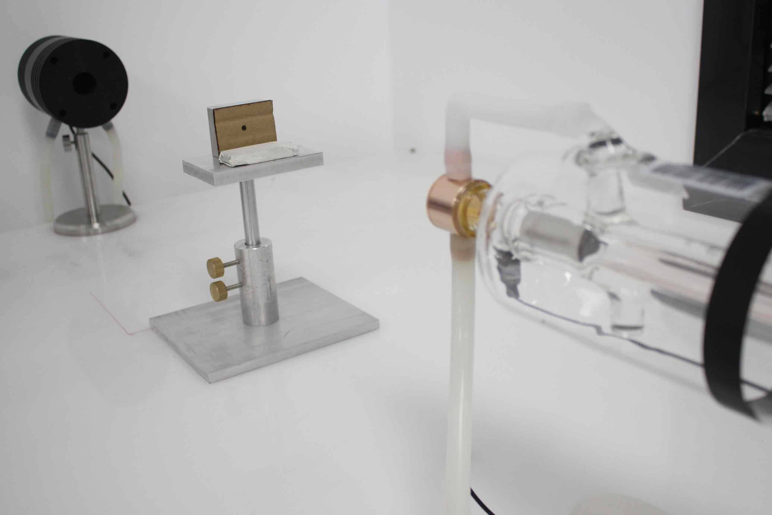
Circuit Wiring
For the collection vehicle to function properly, the M-Planet staff needs to connect the TT motor that drives the antler rotation to the control board. The circuit connection is as follows:
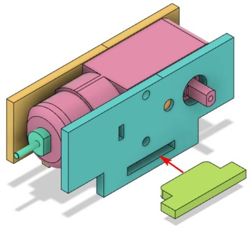
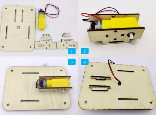
Structural Assembly
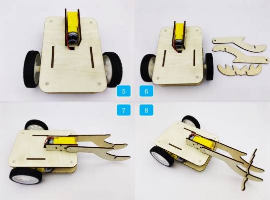
With the circuit connections determined, the M-Planet staff can proceed with the model assembly according to the following steps:
(1) Locate the new base chassis roof panel and related parts for the motor bracket.
(2) Assemble the TT motor and motor bracket together.
(3) Install the motor bracket onto the base chassis roof panel.
(4) Secure the motor bracket with a pin.
(5) Remove the original base chassis roof panel, connect the TT motor driving the antler to the control board, and then install the new roof panel.
(6) Locate the antler-related components.
(7) Attach the vertical antler to the TT motor.
(8) Secure the horizontal antler onto the vertical antler.
Summary
With these steps completed, the collection vehicle is now ready for use. In this process, we have learned new skills such as the B-spline tool and editing nodes, which will undoubtedly help us create more diverse and interesting designs in the future. Congratulations on finishing this project, and keep exploring the world of design and fabrication!
Thought Expansion
The collector vehicle designed in this project has a simple yet practical structure, making it easy to collect energy stones. Do you have any other design ideas?


.png "laser cutter Globle")


