Origin of the Project

With the efforts of the previous designers, the construction of the energy stone collection arena facilities is progressing smoothly. After successfully designing mission vehicles such as mining cars and dump trucks based on the base vehicle, the designers now need to complete the final task: lifting the energy stones from the warehouse to the energy center located at a high point in the arena.
It’s time for our mighty Hercules—the amazing crane to make its appearance. Look at its long crane arm, thick cable, and gigantic hook that can easily lift energy blocks from the ground to a high position. Let’s take a look at how the designers accomplished this design task.
Determining the Design Plan
Analyzing the Work
By observing cranes in real life, we can see that they often work in ports, construction sites, and other locations. They are primarily used as large-scale mechanical equipment for lifting, handling, and hoisting heavy objects. Their working characteristics include the ability to continuously perform lifting, handling, and unloading of heavy loads. Cranes are also known as wheeled cranes, characterized by their flexibility in movement. In contrast, tower cranes are often seen in construction sites, used for building houses. Based on the requirements of this design task, young designers can imitate the structural composition of cranes to design a crane device capable of lifting energy blocks.
Before starting the design, let’s first analyze the crane’s structure. As mentioned earlier, its main features are the ability to lift, handle, and unload. The handling work can be done by the wheeled chassis, while the lifting and unloading actions require the boom. Therefore, when designing the crane model, the design can be divided into the vehicle structure that realizes the movement function and the lifting structural components that realize the lifting function.
Since we have already designed and completed the basic vehicle chassis in previous chapters, for this chapter’s crane design, we only need to focus on designing the lifting structure. By designing corresponding mortise holes on the vehicle body, the lifting structure can be fixed onto the cart. Therefore, the lifting structural components are the focus of this chapter’s design.
The following figure is a mind map for the crane’s design.
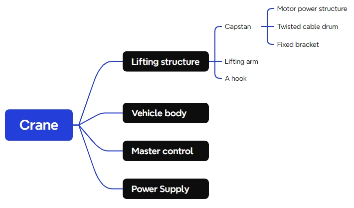
Through observation, it can be seen that the lifting mechanism basically consists of three parts: a winch, a crane arm, and a hook. The winch is composed of a motor power structure, a winch drum, and a fixed bracket. By installing the completed lifting structure onto the basic cart, the crane model can be constructed.
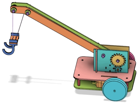
Materials List
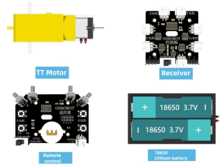
After analyzing each part of the crane, the following materials list has been determined:
No.
Name
Quantity
1
Basic Vehicle Model (for reference)
1
2
2.4G Receiver
1
3
TT Motor (1:220)
3
4
7.4V Lithium Battery
1
5
Basswood Plywood Board (40cm x 60cm x 3mm)
1
6
M3 Flathead Screws, Nuts, Copper Columns
Several
7
R3080 Nylon Rivets
2
8
Cable Ties
2
No. | Name | Quantity |
1 | Basic Vehicle Model (for reference) | 1 |
2 | 2.4G Receiver | 1 |
3 | TT Motor (1:220) | 3 |
4 | 7.4V Lithium Battery | 1 |
5 | Basswood Plywood Board (40cm x 60cm x 3mm) | 1 |
6 | M3 Flathead Screws, Nuts, Copper Columns | Several |
7 | R3080 Nylon Rivets | 2 |
8 | Cable Ties | 2 |
Structural Design of the Project
Creating a Component List
Based on the observational analysis of the crane and the materials list, a structural component list for the project design has been determined, consisting of a total of four parts.
Part No. | Name | Quantity | Function |
1 | Winch | 1 | Fixes the boom and adjusts the length of the lifting rope by rotating, allowing the hook to ascend or descend. |
2 | Boom | 1 | Extends to position the hook over the object to be lifted. |
3 | Hook | 1 | Used to connect to the object to be lifted. |
4 | Base Chassis | 1 | Allows the crane to move from one location to another. |
Laser Modeling
After determining the component list, we can clarify our thinking and proceed with laser modeling.
- Drawing the Winch
A winch is a device used to pull vehicles or boats manually or with mechanical power, commonly seen in traction applications such as docks or trailers. Its appearance is as shown in the figure below:
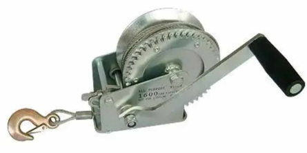
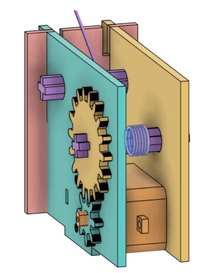
Unlike winches in real-life applications, the primary role of the winch in this crane design is to control the release and retrieval of the lifting rope. The crane winch uses a motor to achieve this, requiring the design to incorporate a motor mounting hole and the winch to be fixed onto the base chassis. The winch can be divided into three parts: motor drive structure, cable drum, and fixing bracket. To ensure that the lifting speed of the rope is not too fast, we need to design a reduction gear within the motor drive structure to slow down the speed.
With an understanding of the components of the winch structure, let’s proceed with the design. A sketch of its structural design is shown in the figure below:
- Fixing Bracket
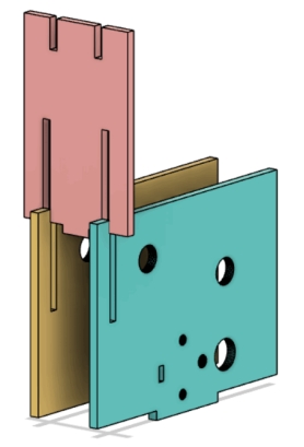
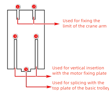
The fixing bracket is composed of three wooden boards. Two of them are located on either side of the motor to secure it, referred to as motor fixing plates. The third board is inserted perpendicularly to the motor fixing plates, providing support for the boom, known as the boom support plate. Tenons are designed under each of the three boards of the fixing bracket, allowing for secure installation onto the base chassis.
- Motor Fixing Plate
Let’s start with the design of the motor fixing plate. Its appearance and structure are shown in the figure below:
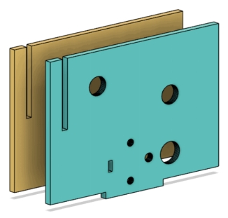
(1) Open LaserMaker and select the “Rectangle” tool from the “Drawing Toolbox” to draw a rectangle with a width of 88mm and a height of 64mm.
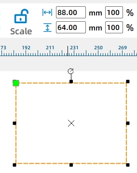
The following figure Drawing the Rectangle
Subsequently, we need to add motor mounting holes to the rectangular board.
(2) From the “Open-source Robotics Hardware” module in the library, select the “TT Motor” and drag it onto the rectangle completed in the previous step. To facilitate operations, we need to treat the entire TT motor as a single unit. This can be achieved by selecting the entire TT motor, right-clicking, and choosing “Group” from the pop-up menu.
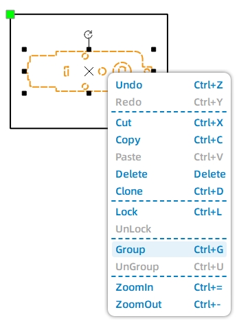
After grouping, the motor graphic can be easily repositioned. Place the motor at the center of the bottom of the fixed wooden board.
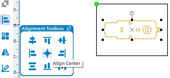
(3) Use the “Selection” tool to select the rectangle and the grouped motor graphic. Then click on the “Alignment” tool in the toolbox and select “Horizontally Center Align” and “Bottom Align.” Through this operation, the motor will be positioned at the center and bottom of the rectangle.
With the motor position determined, we now need to design a tenon for the fixing plate. This tenon will allow for easy installation of the fixing plate onto the base chassis.
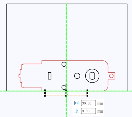
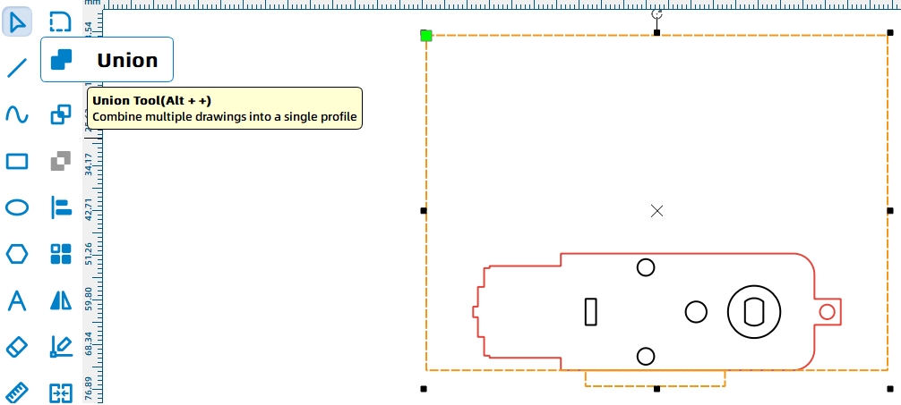
(4) Draw a rectangle with a width of 30mm and a height of 3mm, and position it at the centered bottom of the fixed wooden board. Then select both the large rectangle and the tenon rectangle simultaneously, and use the “Union” tool to merge them into a single entity.
To ensure that the lifting speed of the rope is not too fast, a reduction gear system needs to be designed for the cable drum. This reduction system consists of a small gear driving a large gear. The small gear is mounted on the motor shaft, while the large gear is mounted on the cable drum, forming the motor drive structure of the winch.
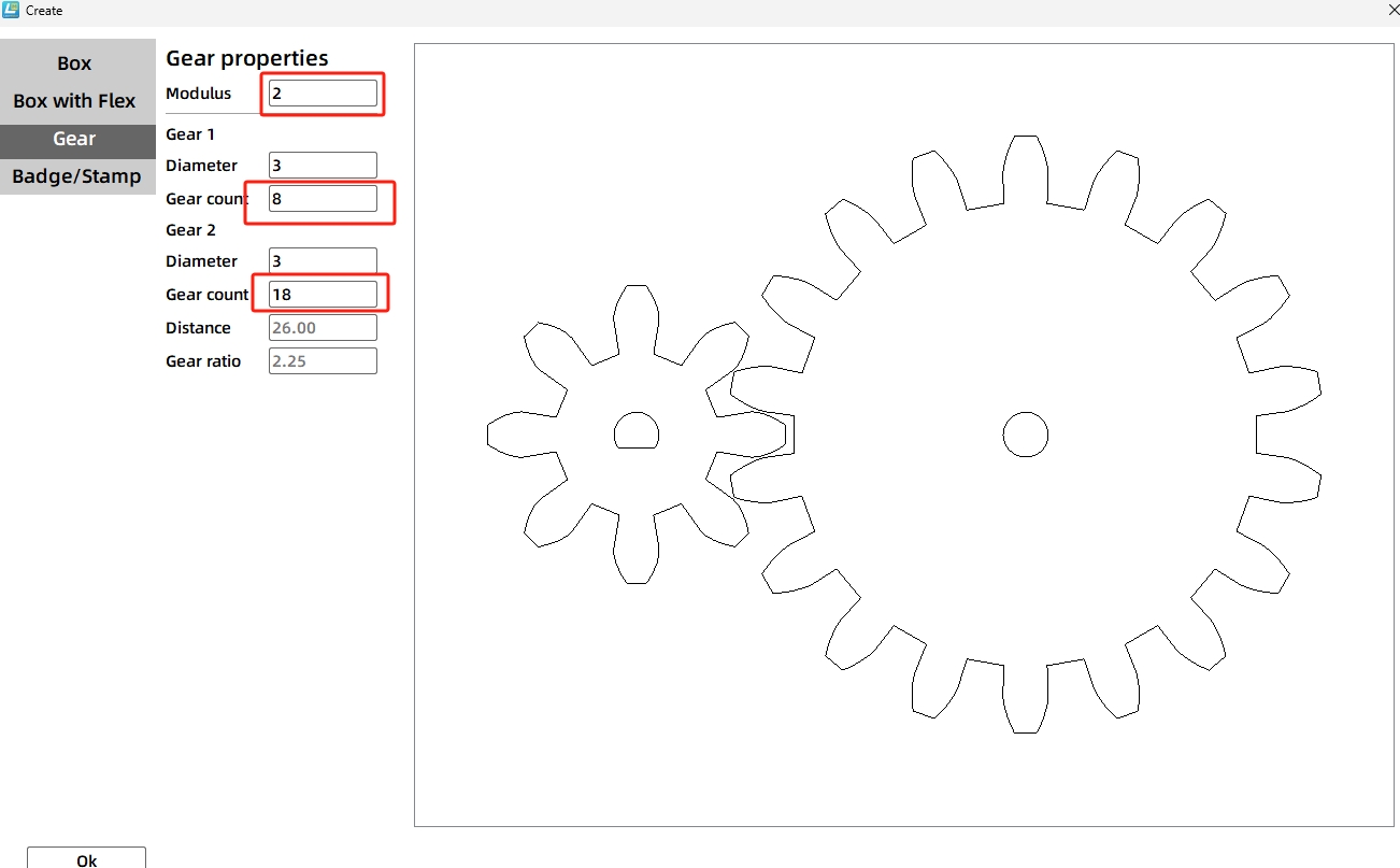
(5) Click on the “One-Click Fabrication” menu in the toolbar and select “Modular Gear” in the pop-up window. Set the number of teeth for the small gear to 8, the number of teeth for the large gear to 18, and the gear module to 2 (the module is a technical term and can be simply understood as the gears with the same module can mesh and transmit motion). The default diameter of the gear shaft hole is 3mm. The gear parameters are shown in the following figure. Click the “Confirm” button to generate the graphics of the two gears.
Using the one-click fabrication function, two gears are generated with the small gear’s center bearing hole corresponding to an N20 motor and the large gear having a circular hole. Based on the project’s requirements, the small gear connects to the motor shaft. Now, we need to replace the small gear’s shaft hole with the TT motor’s shaft hole shape. Here’s how to adjust the shaft hole:
(6) Delete the N20 motor shaft graphic from the small gear’s center. From the “Mechanical Parts” library, select the “TT Hole” graphic, drag it onto the canvas, and place it at the center of the small gear. When dragging the graphic to the center of the small gear, two green intersecting guide lines will appear, indicating it’s centered. Release the left mouse button.
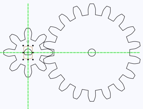
The large gear connects to the cable drum, and since the drum’s shaft is designed as a cross shaft, the shaft hole of the large gear also needs to be modified to a cross shaft hole. Next, we’ll add a cross shaft hole to the gear. The structural appearance is shown in the following figure:

(7) Select the “Rectangle Tool” and draw two rectangles with a width of 2.7mm and a height of 8mm. Rotate one of the rectangles 90 degrees so that the two rectangles are perpendicular to each other.
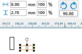
Afterward, the two perpendicular rectangles need to be combined into one.
(8) Select both rectangles and click “Horizontally Center Align” and “Vertically Center Align” from the Alignment Toolbox. This will create a cross-shaped figure. Then click “Union” to merge the shapes and replace the circular hole in the middle of the large gear with the cross-shaped figure.
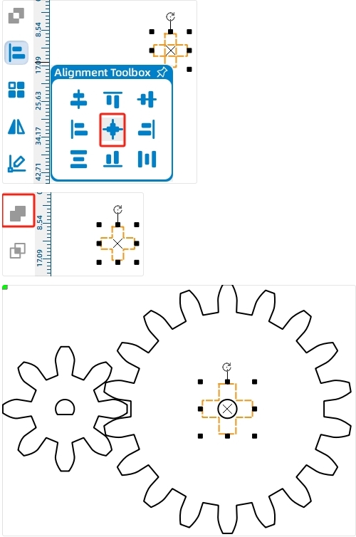
Next, we will place the created gear set onto the wooden board graphic where the motor is fixed, so that we can determine the drilling position for the cable drum shaft.
As we know from earlier, the small gear is mounted on the motor shaft. We can align the shaft hole of the small gear with the motor shaft hole, which will then determine the position of the large gear based on the small gear’s placement. Now, we will rotate and move the graphics to position the small gear beneath the large gear, noting that the shaft hole of the small gear needs to be rotated 90°.
(9) Select both gear graphics and rotate them -90 degrees to position the motor-connected small gear beneath the large gear. Rotate the TT hole position 90 degrees using the same method.
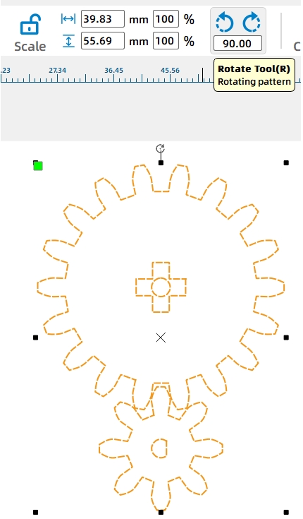
Next, we will group the gear set graphics and move them onto the motor mounting plate. While placing, slowly move the graphics until the TT motor hole of the large gear aligns with the corresponding TT motor hole on the motor mounting plate.
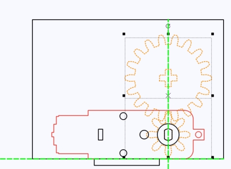
To allow the cross shaft to rotate smoothly, a circular hole with a diameter of 8.6mm needs to be designed around the cross shaft. It’s important to note that this circular hole should be placed on the motor mounting board, not on the gears.
Using the “Ellipse Tool” in the toolbar, draw a circle with a diameter of 8.6mm and position it at the center of the small gear, enclosing the central cross-shaped hole graphic.
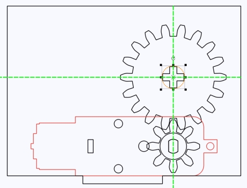
After placement, move the gear reduction set graphic aside to reveal the motor mounting board with the newly added hole. The TT motor graphic in the library includes a TT hole graphic, which can be deleted directly.
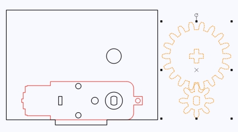
Now, we need to design a mortise in the mounting board to enable it to be joined with another perpendicular wooden board.
(10) Drag a guide line and align it tangent to the left side of the motor. Then, use the “Rectangle Tool” to create a rectangle with a width of 2.7mm and a height of 32mm. Position the rectangle along the guide line on top of the mounting board graphic.
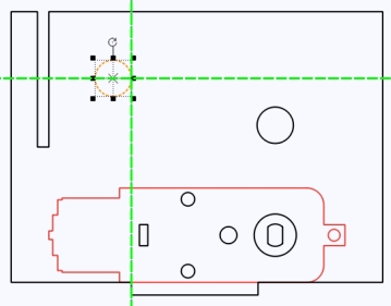
Then, using the “Subtraction” tool, a mortise can be created in the motor mounting board. The purpose of this mortise is to insert a wooden board perpendicular to the two parallel motor mounting boards, which will serve as support for the boom.
Apart from fixing the motor, the winch mounting board also needs to connect to the boom. Now, a circular hole needs to be created on the mounting board for this connection.
(11) Place a circle with a diameter of 8.6mm in the centered position to the right of the mortise slot created in the previous step.
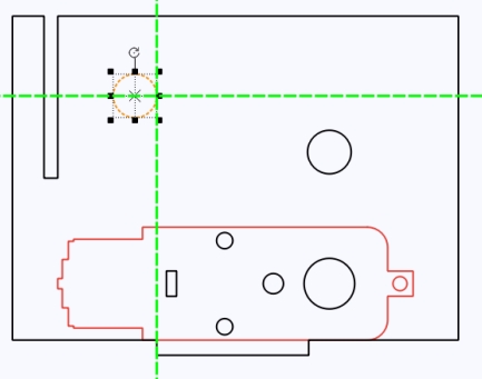
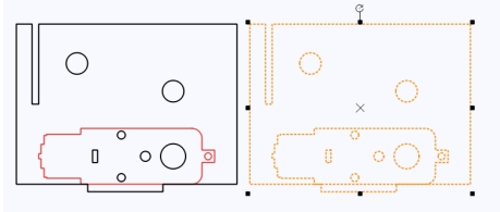
Now, the motor mounting boards on both sides are complete. Since each side of the motor requires a mounting board, we can duplicate the first one to create the second one.
- Boom Support Board
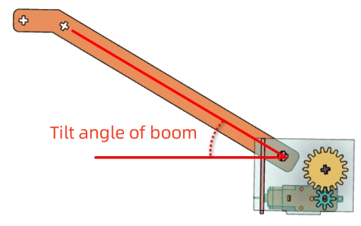
In real-life cranes, the boom can adjust its angle. However, to simplify the design, we’ll fix the boom at a specific inclined angle. The motor mounting board can then serve as the boom support board. The angle between the horizontal direction of the support board and the boom connection hole determines the inclination of the boom.
To better support the boom, a vertical boom support board can be added between the two motor mounting boards, and the wooden boards can be connected through a mortise and tenon joint.
(1) First, use the “Rectangle Tool” to draw a rectangle with a width of 40mm and a height of 64mm. Then, create a mortise with a width of 2.7mm and a height of 32mm within the rectangle.
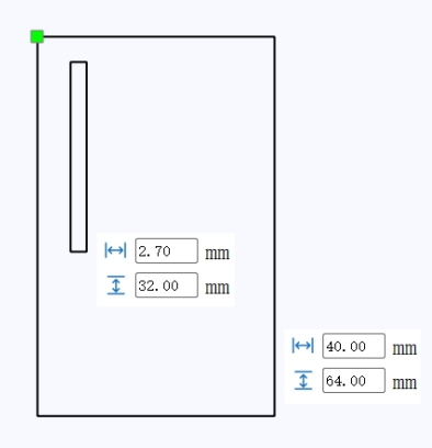
To join with the two motor mounting boards, we’ll duplicate and add another mortise using a rectangular array. The benefit of using a rectangular array is that we can set the number of items and translation distance without manual positioning adjustments, making the operation more convenient.
(2) Select the “Rectangular Array” tool, and in the pop-up window, set the number of horizontal items to 2 and the horizontal spacing to 20mm. This is because the width of the motor body between the two shafts is approximately 20mm, meaning the distance between the two mounting boards is 20mm. Correspondingly, the distance between the mortises on this support board should also be 20mm.
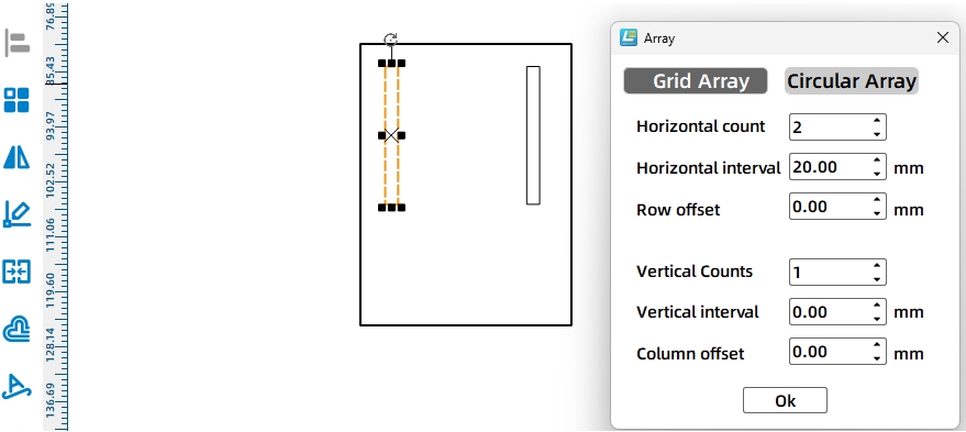
(3) Select both rectangles and align them vertically centered at the bottom. Then, perform a subtraction operation on each rectangle to create the mortises for connecting with the motor mounting boards.
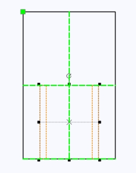
(4) Next, let’s draw the mortises for connecting to the boom.
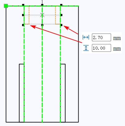
Using the same method, add two more mortises with a width of 2.7mm and a height of 10mm at the top of the rectangle, as shown in the figure.
(5) Next, add a tenon to the support board for connecting to the base cart’s top plate.
Use the “Rectangle Tool” to draw a rectangle with a width of 10mm and a height of 2.7mm, centered below the figure completed in the previous step. Then, select these two shapes and click the “Union” tool to merge them.
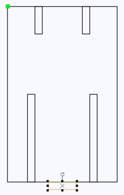
(6) Finally, select each of the four elongated rectangles from the above image individually and then click the “Subtraction” tool to obtain the final boom support board.
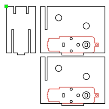
- Winch Drum
After completing the design of the fixed support frame, we’ll proceed to design the winch drum. The winch drum is a functional device that passes through the motor mounting boards and is driven by the motor to realize the retraction and release of the cable. It can be designed with a cross-axle appearance.
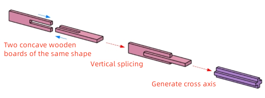
As can be seen from the partial view, a cross-axle is composed of two wooden boards joined together. The winch drum and boom require a total of 4 such cross-axles, meaning we need to design 8 interlocking wooden boards.
(1) Since the previous cross-axle hole width was 8mm, considering laser cutting losses, we can artificially increase the cross-axle width by approximately 0.3~0.6mm. Using the “Rectangle Tool”, draw a rectangle with a width of 8.4mm and a height of 40mm. Then, draw a small rectangle with a width of 2.7mm and a height of 20mm. Select these two rectangles and use the “Align Toolbox” to horizontally center-align and top-align them. Choose the smaller rectangle in the middle and click the “Subtraction” tool to obtain one side of the cross-axle shape.

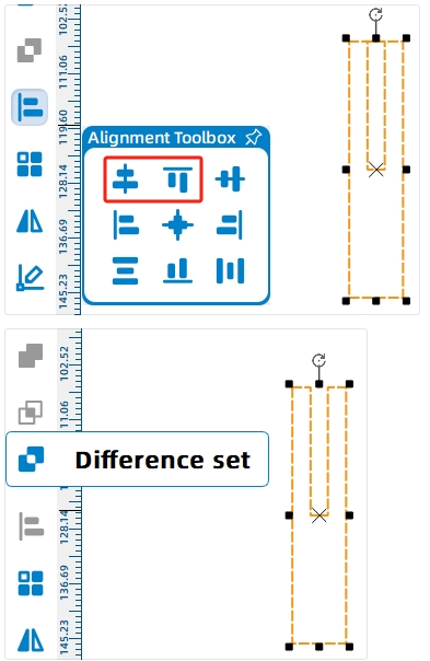
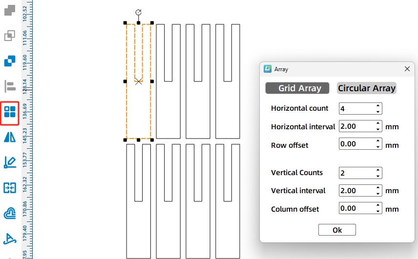
Since we need 4 cross-axles, and each cross-axle is composed of 2 concave-shaped pieces, we need a total of 8 such pieces. We can use the “Rectangular Array” tool to generate identical shapes.
(2) Select the shape and click “Rectangular Array”. Set the parameters to complete the creation of the cross-axles.
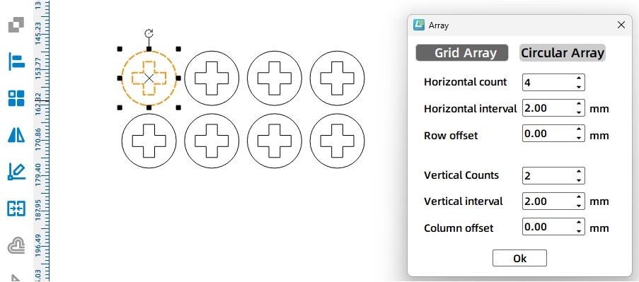
(3) After creating the cross-axles, to prevent misalignment or detachment during rotation, we can design circular axle sleeves with cross-axle holes. Draw a 15mm-diameter circle using the circle tool, then copy and move the cross-axle hole from the boom to the center of the circle, as shown.

(4) Select the shape completed in the previous step and use the “Rectangular Array” tool to generate 8 circular axle sleeves.
- Drawing the Boom
When designing the boom, it is visually composed of two sections: a long arm and a short arm. The short arm is horizontal, while the bottom of the long arm connects to the winch structure at a certain inclined angle. One end of the cable connects to the hook, and the other end connects to the winch drum. The rotation of the winch drum drives the lifting and lowering of the hook.
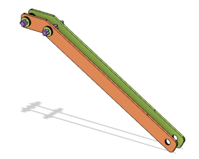
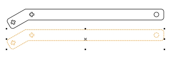
As can be seen from the figure, the boom is composed of two identical wooden boards. Let’s take a look at how the boom is designed:
(1) Use the “Rectangle Tool” to draw two rectangles of different lengths. The longer rectangle represents the long arm, with dimensions of 250mm wide and 20mm tall. The smaller rectangle represents the short arm, with dimensions of 40mm wide and 20mm tall.

(2) Now, we need to rotate and combine the long arm and the short arm. Select the smaller rectangle using the “Selection Tool” and enter -30° in the rotation angle setting at the top of the menu bar. Then click the rotate button, and the rectangle will rotate 30 degrees counterclockwise.
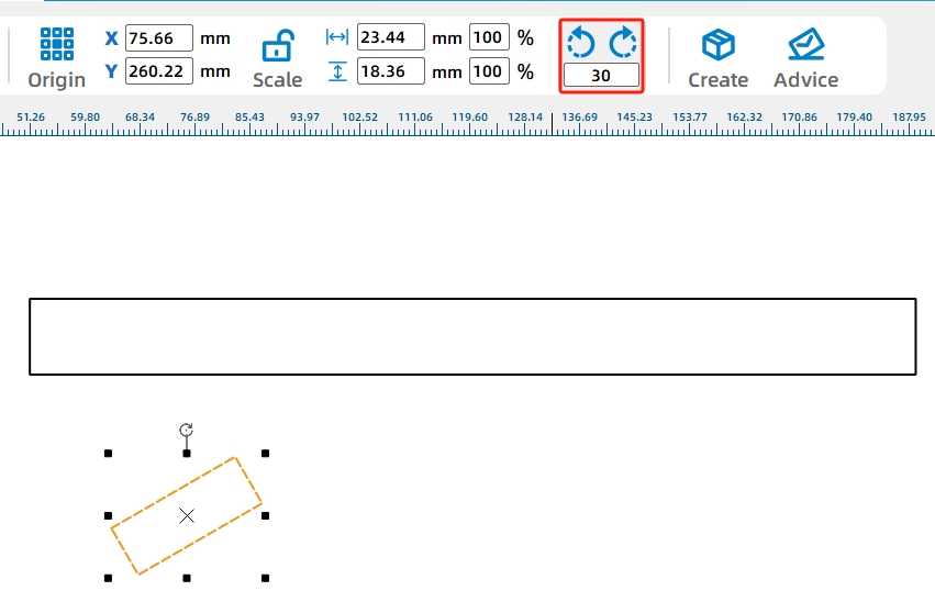
(3) Drag the rotated rectangle with your mouse to align its top corner with the top corner of the long rectangle, as shown in the figure below.

Select both rectangles and click the “Union” tool to merge them into a single unit. This completes the external design of the boom.
Next, we’ll design the axle holes for securing the boom. These holes can be cross-shaped or circular. Cross-shaped holes provide better fastening security, while circular holes offer more freedom of movement. Here, we’ll design two cross-shaped axle holes on the short arm of the boom to redirect the cable’s direction. A circular hole will be designed on the bottom of the long arm to simplify installation.
(4) Use the “Rectangle Tool” to create two rectangles with a width of 2.7mm and a height of 8mm. Rotate one of the rectangles 90 degrees. Then, select both rectangles and click “Align” from the toolbox, choosing “Horizontal Center Alignment” and “Vertical Center Alignment” options to create a cross-shaped axle hole.
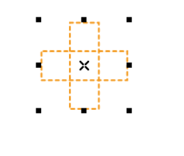
(5) Duplicate the cross-shaped hole and place the two holes at the front end of the boom graphic. Then, using the “Ellipse Tool”, draw a circular hole with a diameter of 8mm and position it at the rear end of the boom.
This completes one side of the boom.

(6) Select and duplicate to create another boom graphic.
- Drawing the Hook
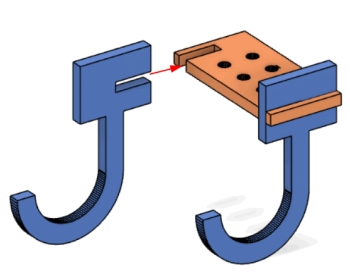
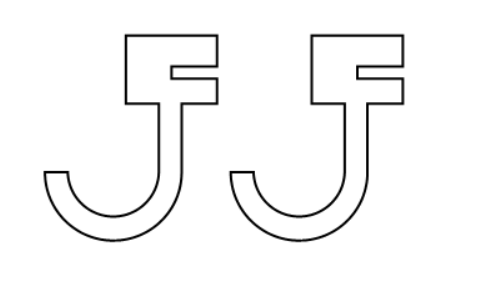
The hook is designed in the shape of a capital letter ‘J’, composed of two curved wooden plates and one rectangular wooden plate. The rectangular plate has six holes reserved, with the middle two holes used to connect the cable, and the remaining four holes for adding screws and nuts to increase the weight of the hook. The curved hooks and rectangular plate are assembled together through mortise and tenon joints.
(1) To start, we’ll draw the rectangular wooden plate for the upper part of the hook. Use the “Rectangle Tool” to draw a rectangle with a width of 20mm and a height of 40mm. Then, use the “Ellipse Tool” to draw a circle with a diameter of 3mm. Select the circle and click the “Rectangular Array” tool. Set the horizontal count to 2, horizontal spacing to 8mm, vertical count to 3, and vertical spacing to 8mm to generate 6 circular holes.
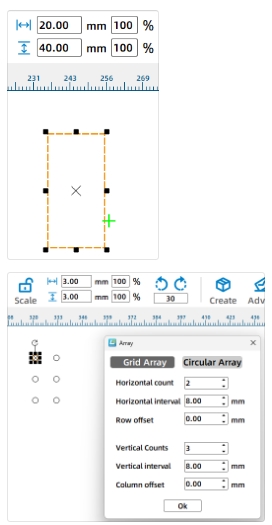
(2) After grouping the six circular holes, continue to select the rectangle you just drew. Click the “Horizontal Center Alignment” and “Vertical Center Alignment” options in the “Align Toolbox” to get the following shape.
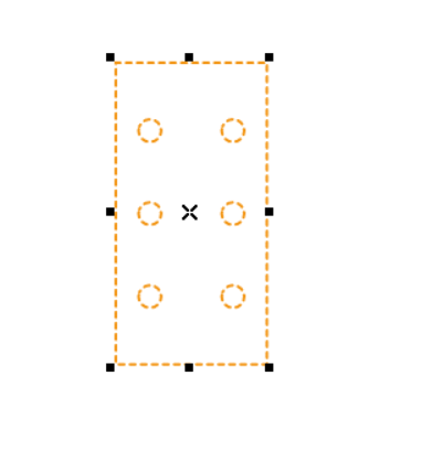
Next, we’ll add two mortise holes on both sides of the graphic to connect the wooden plates of the hook section.
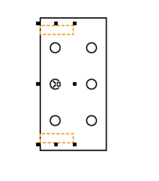
(3) Use the “Rectangle Tool” to draw two rectangles with a width of 10mm and a height of 2.7mm. Align the two rectangles vertically with a vertical distance of 30mm. Center the two rectangles along the left side of the outer large rectangle.
Next, we’ll continue designing the remaining part of the hook, which is shaped like a capital letter ‘J’. Here, you can think about different ways to achieve this design. One way is to directly input a capital ‘J’, which is a good idea if you’re interested in trying it out. However, I’ll introduce a more conventional method by combining a semicircle with a rectangle to form the shape of a ‘J’.
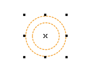
(4) Use the “Ellipse Tool” to draw two circles with diameters of 30mm and 20mm, and align their centers so they overlap.
(5) Draw a rectangle with a width of 30mm and a height of 15mm, and position it on the concentric circles drawn in the previous step. Make sure the upper edge of the rectangle is tangent to the larger circle, as shown in the figure.
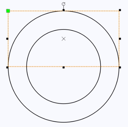
(6) Then click the “Difference” tool to cut half of the concentric circle shape.
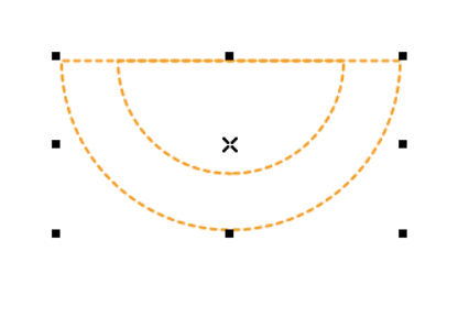
(7) Select the smaller semicircle shape and click “Difference” to obtain a half-ring shape.
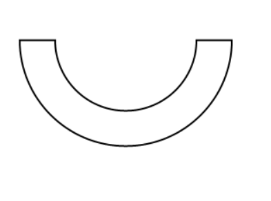
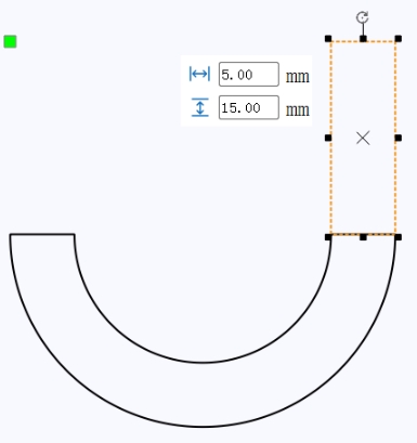
(8) Then, use the “Rectangle Tool” to draw a rectangle with a width of 5mm and a height of 15mm, placing it in the upper right corner of the half-ring, as shown in the figure.
Next, let’s draw the connecting part between the hook and the rectangular wooden plate.
(9) Use the “Rectangle Tool” to draw a rectangle with a width of 20mm and a height of 15mm. Then, draw a smaller rectangle with a width of 10mm and a height of 2.7mm. Select both rectangles and click “Right Align” and “Vertical Center Align” in the “Align Toolbox.”
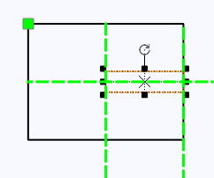
(10) Use the “Union” tool to combine the hook shape with the rectangular shape.
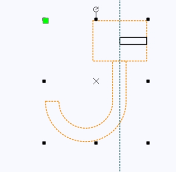
With this, the design of one hook is complete. Depending on the requirements of your project, use the duplication method to create another hook shape.
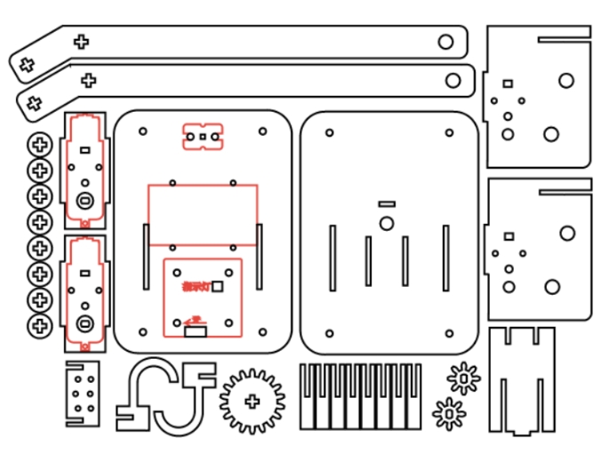
Through the previous designs, all the individual parts of the lifting crane have been completed.
Drag each part from the sketch to the appropriate position, delete any excess parts, change the layers, and arrange them to obtain the final machining drawing.
Laser Processing
(1) Setting Parameters
① Outlining
Double-click the red block in the processing area, select “Material 1: Basswood Plywood” for the material, choose “Outlining” for the processing technique, and set the cutting depth to “0.10”. Click “OK” to confirm.
② Cutting
Double-click the black block in the processing area, select “Material 1: Basswood Plywood” for the material, choose “Cutting” for the processing technique, and set the cutting depth to “3.00”. Click “OK” to confirm.
(2) Starting Fabrication
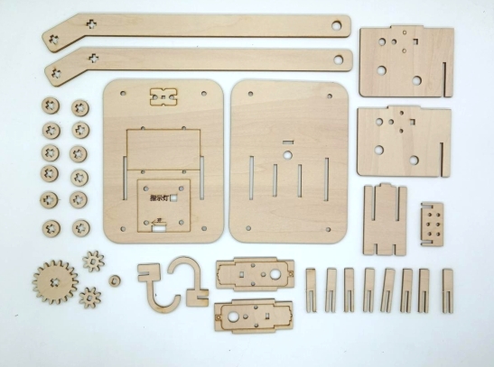
Turn on the power switch of the laser cutting machine and the laser switch. Wait until the “Start Fabrication” button turns blue, then click it. Once the drawing is uploaded to the laser cutting machine, press the “Start” button on the machine’s panel to begin cutting. The completed physical model is shown in the following figure.
Assembling the Model
Circuit Wiring
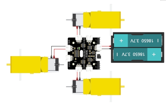
Connect the circuit components according to the following diagram.
Structural Assembly
Secure the TT motor, 1x 18650 battery box, and 2.4G receiver in place using screws and nuts. The specific steps are as follows:
Step 1: Take out the two motor mounting plates that form the rotating structure support, one boom support plate, along with the motor, screws, and nuts.
Step 2: Install the two motor mounting plates on either side of the motor and secure them with screws and nuts. Then, insert the boom support plate into the grooves at the front of the motor mounting plates from top to bottom.
Step 3: Take out the two wooden boards that form the universal joint and the two fasteners with cross-shaped holes.
Step 4: After assembling the universal joint, pass it through the round holes on the motor mounting plates and the fasteners with cross-shaped holes. Ensure that the two fasteners are positioned between the two motor mounting plates.
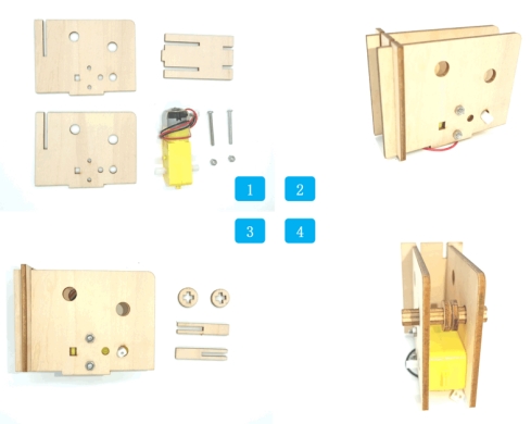
Step 5: Take out the gears and corresponding fasteners.
Step 6: After installing the large gear on the universal joint, add circular fasteners with cross-shaped holes to both ends of the universal joint to prevent the axle from loosening. Install the small gear on the motor’s rotation axis.
Step 7: Take out the parts needed to assemble the lifting arm.
Step 8: Note that the first universal joint at the front end of the lifting arm should also have two fasteners with cross-shaped holes passed through it. After installing the universal joint, use fasteners with cross-shaped holes to secure both ends to prevent misalignment.
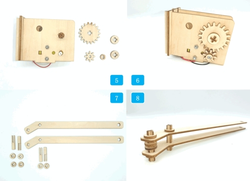
Step 9: Take out the assembled lifting arm, rotating structure support, and universal joints.
Step 10: Use the universal joints to pass through the round holes at the ends of the rotating structure and the lifting arm, securing them together.
Step 11: Take out the upper deck panel of the vehicle body and prepare to connect it with the structure completed in the previous step.
Step 12: Insert the tenon at the bottom of the rotating structure support into the mortise on the upper deck panel of the vehicle body. Pass the motor wires from the rotating structure through the round holes on the upper deck panel.
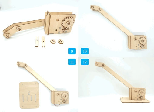
Step 13: Take out the chassis of the small trolley and prepare to install the structure completed in the previous step onto the chassis.
Step 14: First, connect the motor wires from the rotating structure to the “X Motor” connector on the receiver board. Then, combine the tenons on the two motor mounting plates of the trolley chassis with the mortises on the upper panel of the trolley. Secure the upper panel to the octagonal spacer posts on the trolley chassis using four screws.
Step 15: Take out the parts for the hook.
Step 16: Connect the two “J” shaped structures using a mortise and tenon joint. Install four sets of screws and nuts on the round holes on both sides. The purpose is to increase the weight of the hook. Additional nuts can be added based on the actual situation to change the counterweight of the hook. The two round holes in the middle are used to thread the lifting rope through.
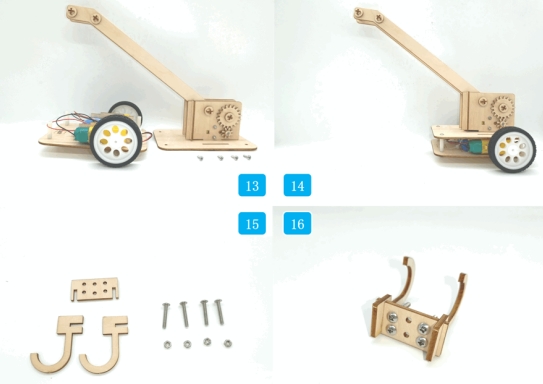
Step 17: Thread the lifting rope through the two round holes in the center of the hook.
Step 18: Pass one end of the lifting rope through the gap between the two circular sleeves on the universal joint at the front end of the lifting arm. Adjust the distance between the two fasteners and clamp the rope with the fasteners. This will connect one end of the lifting rope to the lifting arm.
Step 19: Pass the other end of the lifting rope from the bottom up through the second universal joint at the front end of the lifting arm.
Step 20: After the lifting rope passes through the second joint, connect it to the circular sleeve of the hole on the universal joint of the rotating structure.
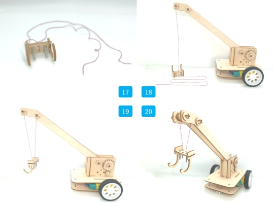
Summary
Through the previous design, we have combined the knowledge of gear transmission and pulleys to complete the construction of a crane. In this project, a wheel axle responsible for reeling in and out the cable is used as a fixed pulley. The cable passes through the fixed pulley, and its two ends are fixed to the hook and the circular sleeve at the end of the lifting arm. Vertical transmission of the gear connected to the motor drives the rotation of the universal joint. As the universal joint rotates, it changes the length of the cable, thus achieving the lifting and lowering of the hook.

Thought Extension
During practical application, despite increasing the weight of the hook, we noticed that when the hook is not attached to an object, it tends to drift during ascent or descent. Do you, dear reader, have a better solution to this issue?
Browse Thunder Laser Bolt >





.png) International
International
 United States
 Brasil
 Canada
 Costa Rica
 Mexico
 Česká
Česká
 Romania
 Polska
 Ireland
 Portugal
 Lietuva
 Россия
 Deutschland
 Britain
 Україна
 France
 Sverige
 Italia
 Norway
 Denmark
 Ελλάδα
 한국
한국
 中国
中国
 ประเทศไทย
 中国香港
中国香港
 Israel
 中國臺灣
中國臺灣
 India
India
 پاکستان
 پශ්රී ලංකා
 ジャパン
ジャパン
 Australia
 New Zealand
 South Africa