There are a lot of amusement programs in the playground, and many small and big friends are able to play from day to night. In order to keep Planet M’s playground open at night, the designers now need to make a colorful light box for the playground.
Determine the design
Analyze the work
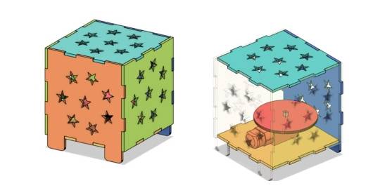
The design of the light box can be based on the lanterns in life, but in order to let more light through, we need to make extra holes in the box, as shown in Figure 3-2. At the same time, a rotating motor is added inside the box, as shown in Figure. 3-3, so that the staff of Planet M amusement park can control the rotation of the lights in the box with the OSROBOT remote control kit, and then they can present the players with a wonderful and varied light show.
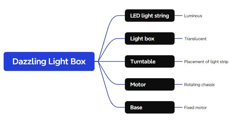
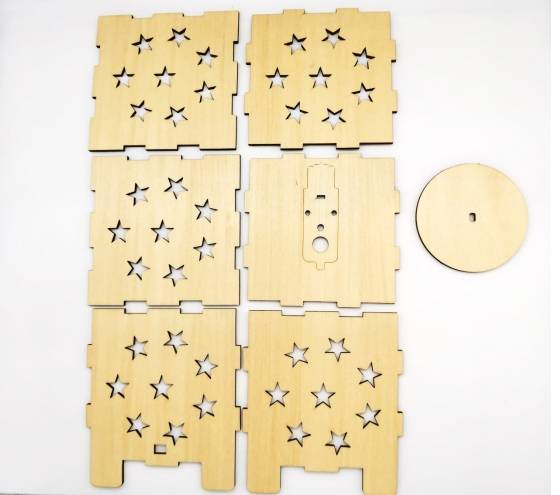
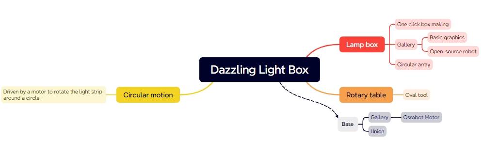
After finalizing the design, we can list the components of the light box, as shown in the following figure.
Equipment list
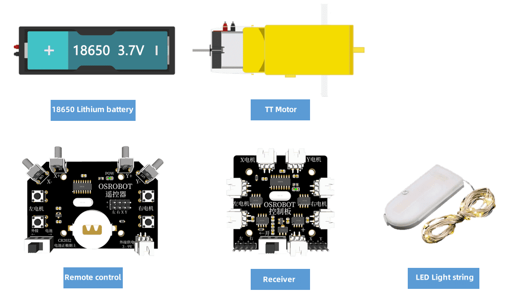
After completing the disassembly and analysis of the structure of the light box, we also need to combine the existing materials of the Maker’s Factory to create a list of equipment, as shown in the following Table and figure.
No.
Name
Quantity
1
2.4G remote control (with battery)
1
2
2.4G Receiver
1
3
TT motor (1:120)
1
4
18650 Battery (with cable)
1
5
Basswood Laminate (40cm*60cm*3mm)
1
6
M3 screws and nuts
Several
7
LED light string
1 pcs
Design of the structure of the work
After preparing the equipment in the list, we can start to design and create the appearance structure of the dazzling light box.
Create a parts list
According to the structure of the light box, we need to further refine the structural parts that need to be designed for the work and create a structural parts list, as shown in the following Table.
Part number
Part name
Number of parts
Function
1
Lamp Box
6
Display Lights
2
Chassis
1
Fixed motor
3
Chassis
1
Placement of LED lights
Laser Modeling
After completing the equipment parts list and the structural parts list, we can begin laser modeling with the Laser Maker software.
Drawing the light box
There are various shapes of lanterns in life, and the shape of the light box can also be varied. From the point of view of the characteristics of the material and the solidity of the work, we can make use of the one-click building function in LaserMaker software (which can quickly draw a planar diagram of the hexahedron) to make a square light box.
(1) Open LaserMaker software, mouse click on the menu bar of the 【One-Click Artifact】, as shown in the following figure.
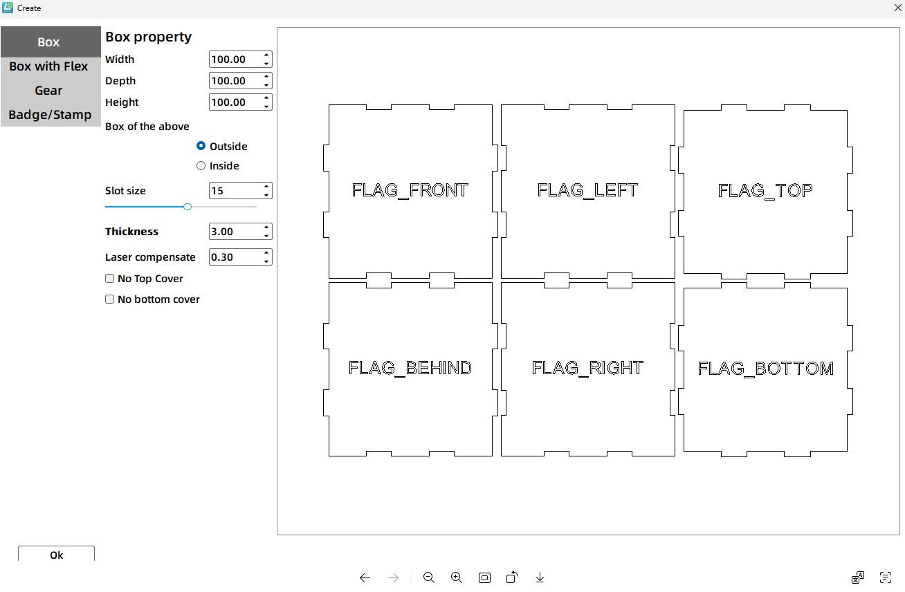
(2) in the left panel of the pop-up window, select the “Right Angle Box” tool. Set the box properties in the middle panel, double-click the corresponding text box with the mouse to modify the length, width and height of the box size, set the value of 100mm, double-click the “notch size” corresponding to the value of the input box, set the size of the 15mm, press Enter to confirm, but also use the “Flat” on the right side of the window to create objects. Window on the right side of the “plane display map” for preview, as shown in the following figure.
Tips: The notch size is the length of the mortise and tenon in the box. Due to the laser compensation value of 1 set, through the [artifacts] drawn by the actual length of the box mortise and tenon is 14.4mm.
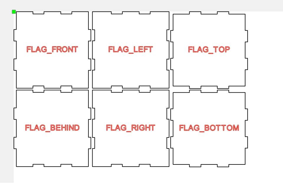
(3) Click the “OK” button, back to the canvas drawing area can be generated as shown in the following figure six sides.
The center of the box panel completed with the [Creator] function will have orientation tips, which is very helpful for the design and production of the model. However, in order to facilitate the drawing of the pentagram graphic on the light box later, you need to move these hint words to the outside of the panel.
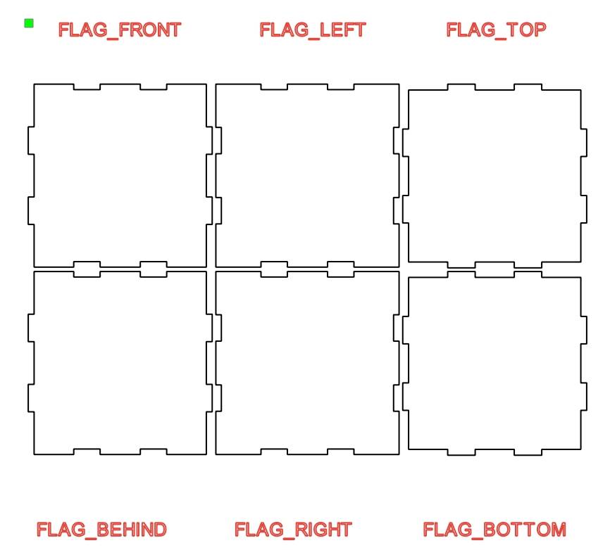
(4) Use the mouse to select and drag and drop the six sides of the box to move the tips to the appropriate location, as shown in the following figure.
Through the creation of objects to complete the drawing of the shell of the light box, the next step is to start the design of various shapes of light transmission holes in the light box, such as “pentagram”.
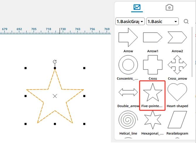
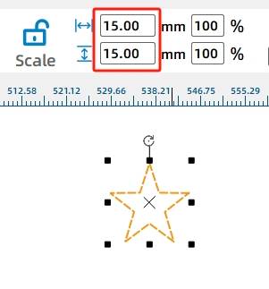
(5) from the Gallery panel [1. Basic Graphics] to find and select the “Pentagram”, click the mouse do not let go of the graphics drag and drop to the canvas, as shown in Figure 3-10. At the same time to adjust the size of the pentagram, click the [isometric] button to unlock, modify the width and height of the graphic value, the value is set to 15mm, as shown in the following figure.
With this method to get a five-pointed star, you can use the next [Array] tool to add more regular arrangement of light box five-pointed star translucent holes.
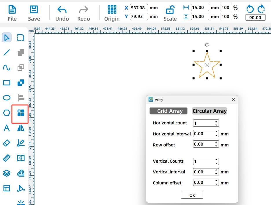
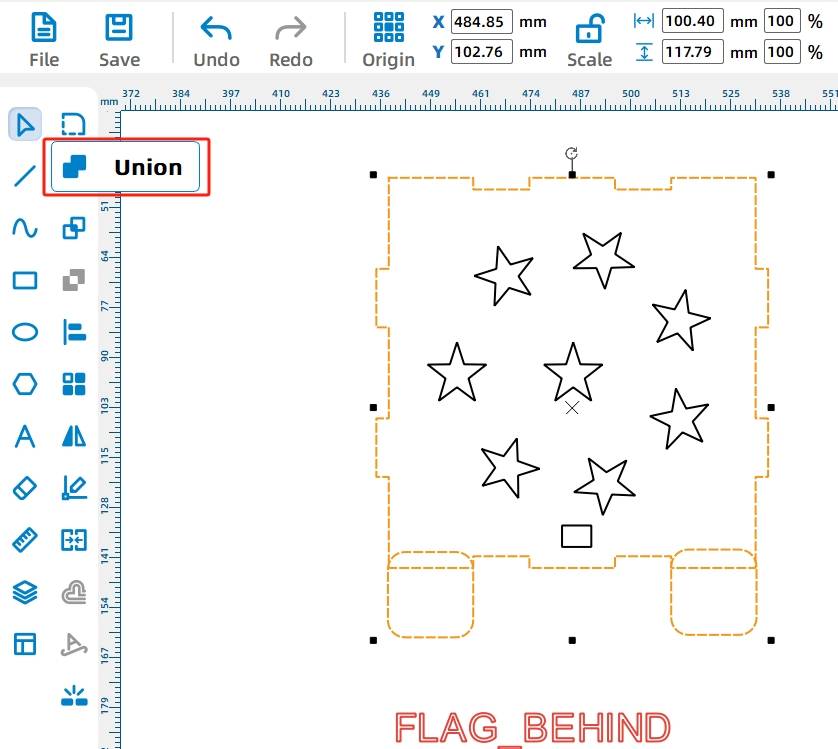
(6) mouse click to select the pentagram, click the left drawing tool [Advanced Tools] in the “ring array” tool, shown in the following figure.
Array tool has a rectangular array and ring array, its attribute parameters can be modified by direct input and fine-tuning the method of the button, the real-time preview effect can help determine the final graphics.
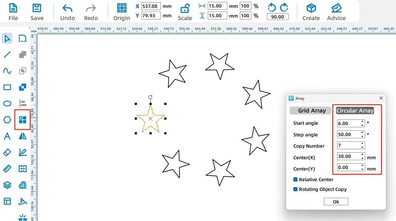
(7) in the pop-up properties window, select the ring array, modify the corresponding parameters in turn: “Start Angle: 6 °”, “Step Angle: 50 °”, “Number of Copies: 7” and “Center Point (X)”. and “Center (X): 30”, as shown in the following figure.
By using the Circular Array tool, we get a circular star map. However, because the pentagram is used as a light transmission hole, it is also necessary to draw another pentagram at the center of the ring star map.
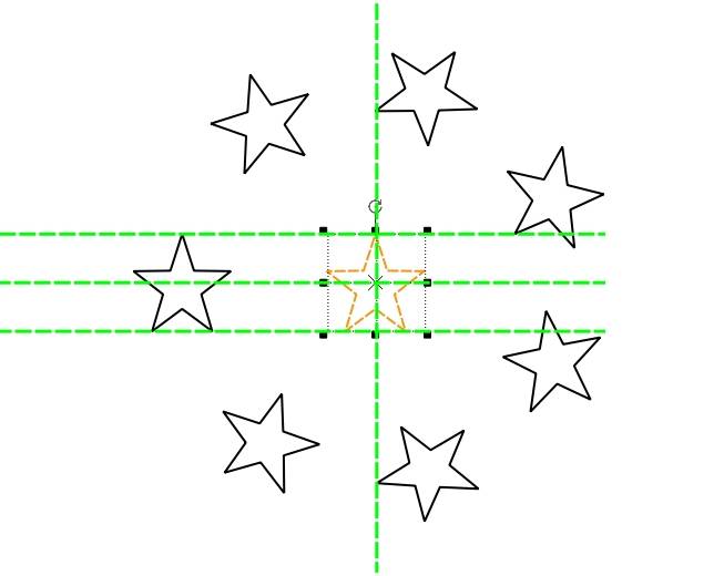
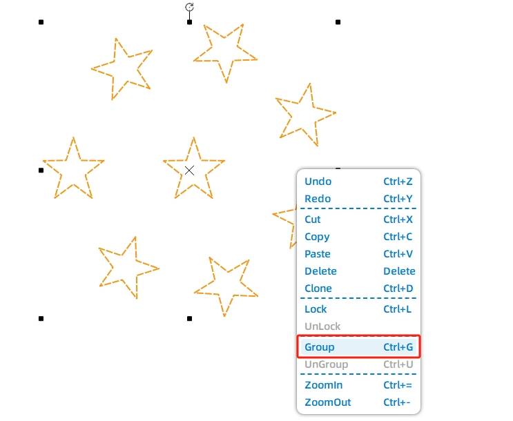
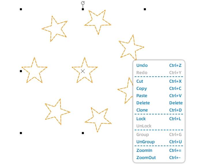
(8) Repeat step (6) to draw a new pentagram, drag the pentagram to the center of the ring star map, as shown in Figure 314. Mouse box the ring star map and then right-click to select the group, as shown in the following figure.
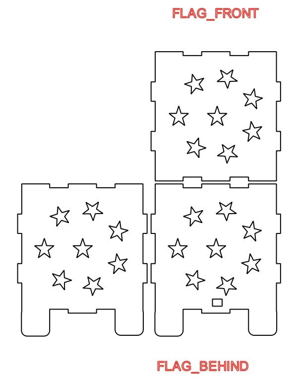
(9) the use of the mouse right-click pop-up window menu in the “Group” and “Copy, Paste”, as shown in Figure 3-16, complete the ring of star charts to regroup and graphic reproduction.
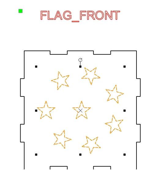
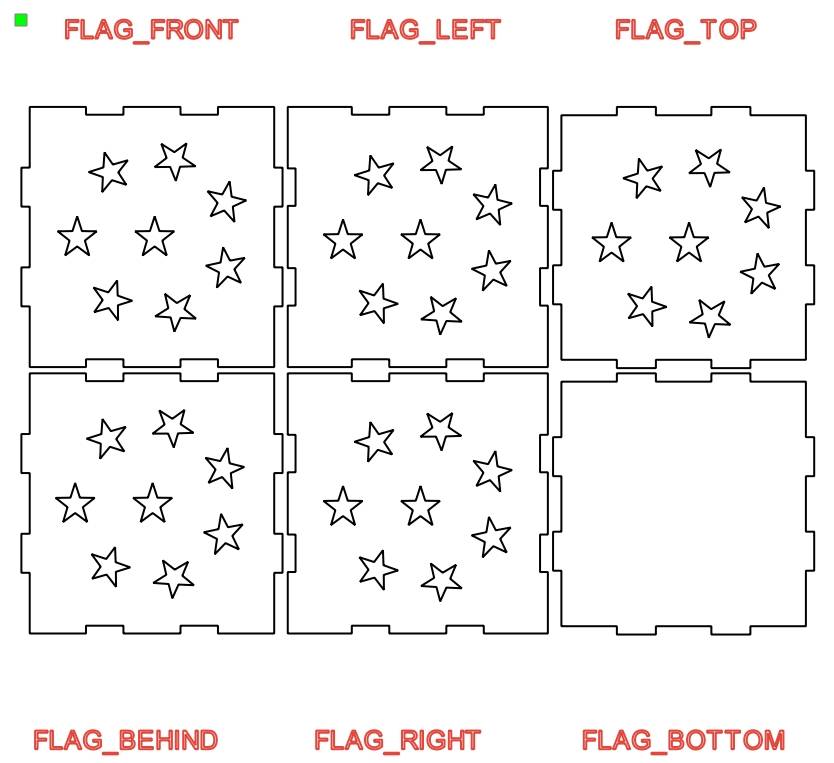
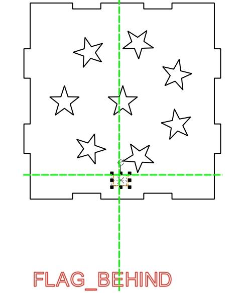
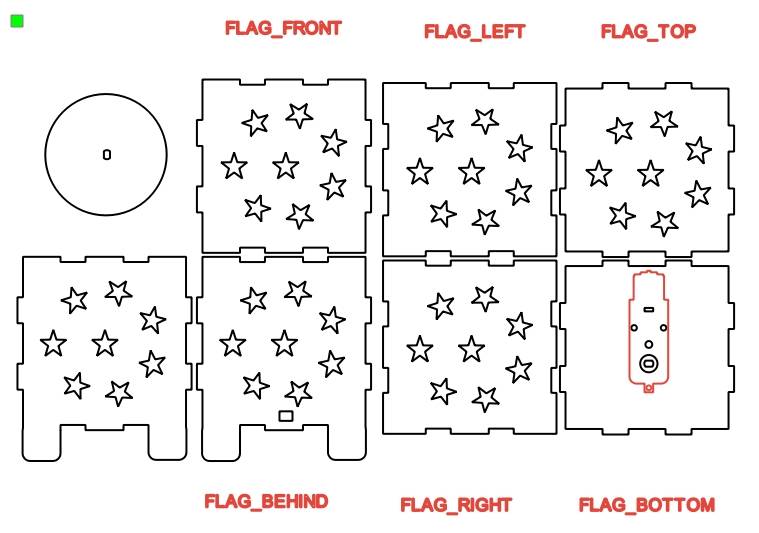
(10) will be reproduced by dragging the graphics to the light box “before” the panel, as shown in Figure 3-17, and repeat the “Paste” operation, the graphics will be dragged to the light box of other panels, as shown in the following figure.
Tips: The “lower” panel needs to install the motor, so the “lower” panel does not need to draw the ring star graph.
Finish adding the light transmission pattern of the light box, and then add the motor fixing holes at the bottom of the light box.
Drawing base
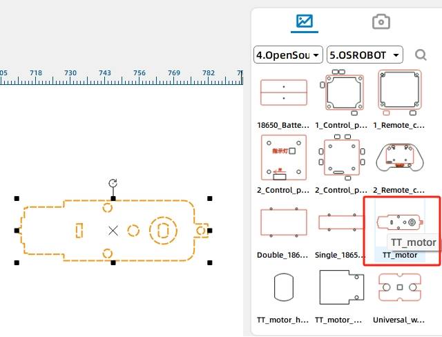
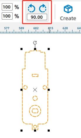
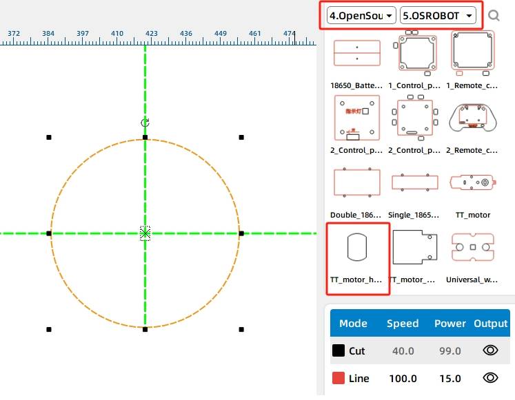
Select the Gallery [8. Open Source Robotics] in the “OSROBOT motor”, click the mouse do not let go of the graphics dragged to the canvas, shown in the following figure.
(2) Move the mouse to the Rotate button and enter 90, click the Rotate button to position the TT motor vertically in the canvas as shown in the following figure.
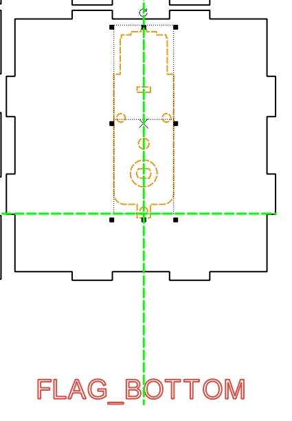
(3) Considering that the bigger the chassis is, the better it is for the placement and rotation of the LED string, so under the premise that the motor can operate normally, we need to place the motor’s rotary hole as close as possible to the center of the “lower” panel. We can first add an auxiliary line, and then use the mouse to drag the motor to the light box “under” the panel, the position adjustment is completed as shown in the following figure.
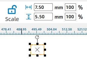
As this work of 2.4G receiver and 18650 lithium batteries on the outside of the light box, so also draw a rectangle in the “rear” panel as a threading hole, easy to connect the circuit.
(4) Click the drawing tools in the [Rectangle Tool], click the mouse without letting go, in the canvas to draw a 7.5mm wide, 5.5mm high rectangle, shown in Figure 3-22. Then use the mouse to drag it to the light box “after” the panel, drag the position shown in the following figure.
At the same time, the base motor needs to be fixed with screws and nuts, which will cause the bottom surface of the box to be unstable. So also need to light box height, here you can draw the light box feet, by increasing the space of the bottom surface to ensure the stability of the light box.
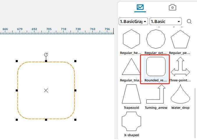
(5) Select the Gallery [1. Basic Graphics] in the “rounded rectangle”, shown in the following figure.
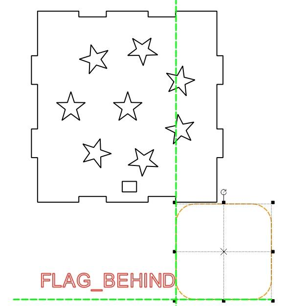
(6) Drag and drop the graphics to the light box “after” the bottom of the panel on the right position, and use the mouse to hold down the right corner of the graphic of the black control point along the diagonal movement, as shown in Figure 3-25, so that the rectangle width with the “after” the panel of the most right-handed “Tenon” consistent, as shown in the following figure.
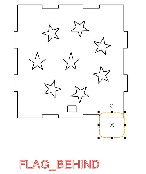
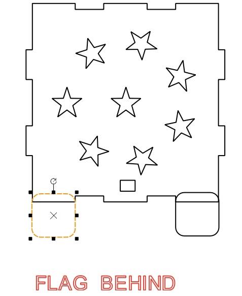
(7) using copy and paste the method of reproducing the second rounded rectangle, and will be placed in the “after” the lower left corner of the panel position, placed in the completion of the following figure shows.
Next, you need to support the feet of the two rectangles and light boxes as a “rear” panel integrated together.
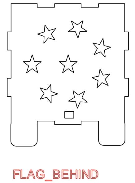
(8) hold down the Ctrl key on the keyboard, the mouse click “after” the panel and the two rounded rectangles, shown in Figure 3-28, and then click the drawing tools in the [and set] will be merged together, shown in the following figure.
(9) observation and comparison found that the mortise and tenon structure of the front and rear panels are consistent, so in addition to repeating the steps (5) (8) to complete the light box “before” the panel of the support foot drawing, you can also copy and paste the way to replicate a “after” the panel, and then remove the threading holes, you can get a support foot “before” the panel, complete the effect shown in the following figure.
Finally, in order to place the string inside the box and rotate it, you need to install a round turntable on the motor shaft.
Drawing light string turntable
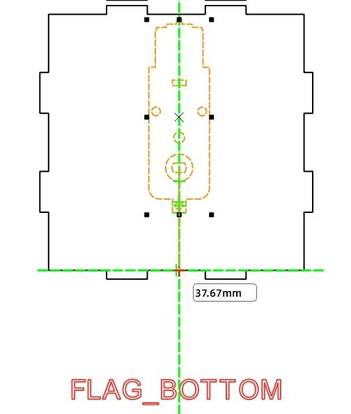
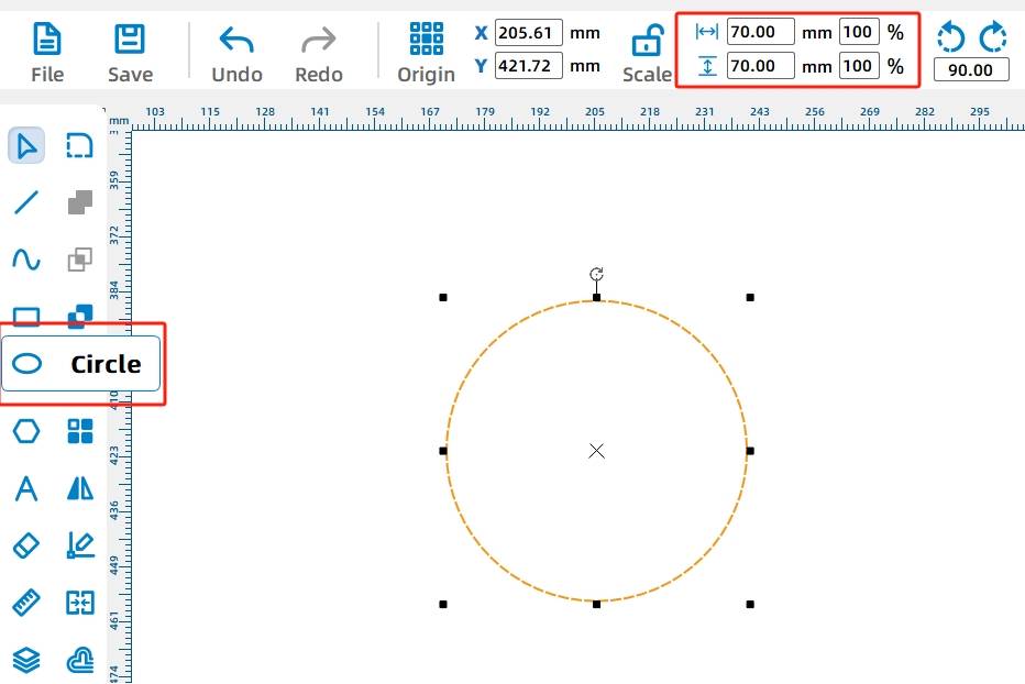
(1) mouse click on the drawing tool in the [Distance Measuring Tool], move the mouse to the center of the circle of the motor graphics, hold down the mouse and move to the edge of the light box, measured the distance between the two points is 37.16mm, as shown in the following figure.
Here the dimension 37.67mm is the maximum radius of the turntable that can be placed on the TT motor shaft. Here the radius of the turntable can be set to 35mm, which means that a circular turntable with a diameter of 70mm needs to be drawn.
(2) mouse click on the drawing tool [Oval Tool], hold down the Ctrl key, in the canvas to draw a diameter of 70mm circle, shown in the following figure.
Next you need to add the motor shaft hole for the turntable, so that the turntable can be installed on the motor.
(3) Select the Gallery [4. Mechanical Parts] in the “TT holes”, drag the graphics to the center of the turntable, shown in the following figure.
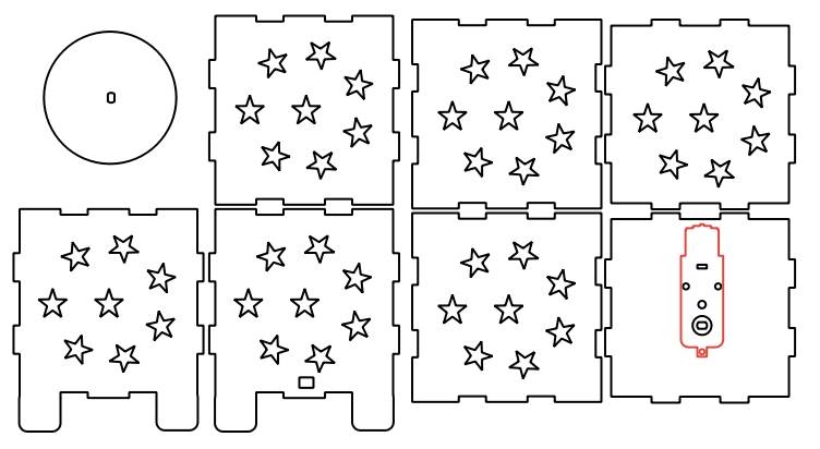
Finally, you also need to delete the redundant text and lines used to assist the drawing. Hold down the Ctrl key on the keyboard, the mouse to select the red labeled text or auxiliary lines, as shown in Figure 3-34. Right-click and select “Delete”, the completion of the effect shown in Figure 335. Finally, click the menu bar in the [File] option, the file “Save”.
Laser Processing
Followed by the designer successfully completed the design drawings, we can carry out physical cutting. The design drawings of this light box include only two processing techniques, tracing and cutting, except for the outline of OSROBOT motor for tracing, the rest need to be cut. According to the model of the laser cutting machine, check the speed and power of the two processes of tracing and cutting. Click on “Simulate Creation” with the mouse to further check and confirm the sequence of processes such as tracing and cutting. Finally, click “Start Creation” to transfer the drawing file to the laser cutting machine. Adjust the laser cutting machine focus, positioning and border, press the start button to complete the work of cutting. The cutting effect of the colorful light box is shown in the following figure.
Assemble the model
After getting the parts processed by the factory, we need to confirm the circuit wiring before we start assembling the light box.
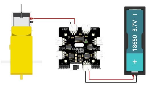
Circuit wiring
In order to facilitate assembly, we need to draw the wiring diagram of the device in advance, as shown in the following figure.
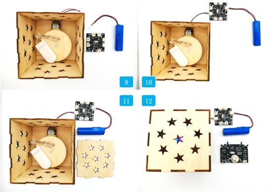
Structure assembly
After clarifying the wiring diagram, we can fix the TT motor, 1 18650 battery box and 2.4G receiver to the corresponding positions with screws and nuts to assemble the light box and chassis, the specific steps are as follows:
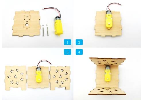
Step 1: Locate the motor, chassis and corresponding hardware.
Step 2: Use screws and nuts to fix the motor to the chassis.
Step 3: Locate the front and rear panels of the light box.
Step 4: Assemble the front and rear panels and chassis together by passing the TT motor connecting wires through the rear panel.
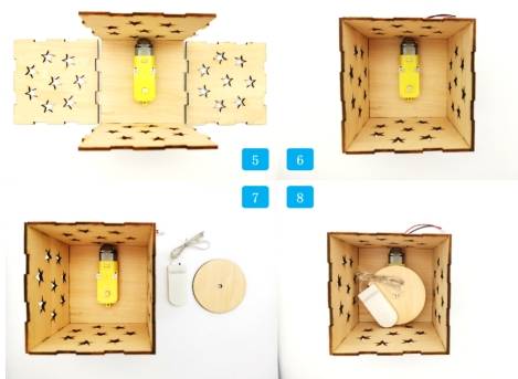
Step 5: Locate the left and right panels of the light box.
Step 6: Assemble the left and right panels to the base plate.
Step 7: Find out the turntable and LED string.
Step 8: Fix the turntable to the rotating shaft of the TT motor and put the LED string on the turntable.
Step 9: Locate the 18650 lithium battery and the 2.4G receiver.
Step 10: Connect the TT motor and 18650 lithium battery to the 2.4G receiver.
Step 11: Locate the upper panel of the light box.
Step 12: Turn on the LED string switch and cover the upper panel.
After finishing the assembly, we still need to debug the light box.
Summarize
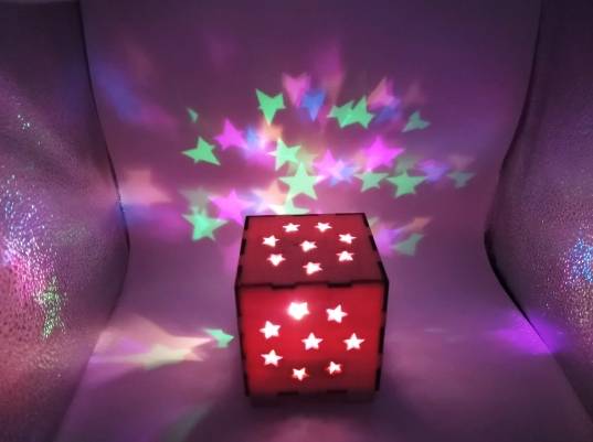
In the production of this work, we have learned the use of LaserMaker software in the ring array and one-click box building, but also further familiarize with the gallery call, graphic size adjustment and other operations, learned to use the [Concatenation Tool] for the light box to add the support feet, a complete experience of the whole process from the design drawings to the production of the physical object, as shown in the following figure.
Planet M playgrounds look dazzling at night with the addition of the Dazzle Light Box. The outstanding project is also recognized by Planet M. Let’s follow the designers as they prepare for the next ride.
Thinking Outside the Box
Guys, in the model assembly and work display, we will find that controlling the brightness of the LED strings requires frequent opening of the light box, but the setting of the laser compensation value in the process of drawing the light box greatly increases the difficulty of opening the light box. Is there any way to improve this situation? For example, design a cover for the light box, and design the appearance of the light box as a gift? Or do you have a better idea? Alternatively you could design some more colorful patterns for the light box.


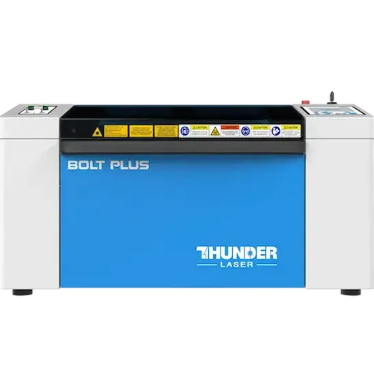

.png "laser cutter Globle")


