Origin of the Project

The first task for the designers is to design a lucky roulette and make its pointer spin successfully. When the pointer stops, based on the game item name corresponding to the area where it lands, it will help players on Planet M choose the game to participate in.
Let’s open the laser cutting software and embark on a magical journey of laser creation, following in the footsteps of the designers. Let’s Go!
Confirming the Design Plan
Analysis of the Work
In daily life, we have all seen the lucky roulette. It consists of a circular disk with many sections of varying sizes, where different types of prizes are set in different areas. When the pointer in the middle of the roulette is spun, it will randomly point to a section, and the player can win the corresponding reward.
Based on the above analysis, we can plan out the basic components of the lucky roulette, as shown in the following figure.
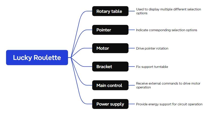
In the Laser Kingdom’s creation factory, we are provided with many innovative materials. Let’s go on a treasure hunt to find the right “ingredients” and create a lucky roulette together.
Materials List
Based on the breakdown and analysis of the lucky roulette, we can use the following materials to create it, as shown in Table 1-1:
Number
Name
Quantity
1
2.4G Remote Control
1
2
2.4G Receiver
1
3
TT Motor
1
4
18650 Battery
2
5
18650 Battery Box
1
6
Basswood Panel (40cm x 60cm x 3mm)
1
7
M3/M4 Screws, Nuts, and Nylon Standoffs
Several
Number | Name | Quantity |
1 | 2.4G Remote Control | 1 |
2 | 2.4G Receiver | 1 |
3 | TT Motor | 1 |
4 | 18650 Battery | 2 |
5 | 18650 Battery Box | 1 |
6 | Basswood Panel (40cm x 60cm x 3mm) | 1 |
7 | M3/M4 Screws, Nuts, and Nylon Standoffs | Several |
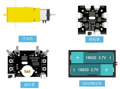
I must highlight the “treasures” of the remote control and receiver. They are indispensable partners that transform manual projects into electric ones, from wired to wireless remote control, enabling more creative works.
After selecting the components, we also need to design a beautiful outer shell for the lucky roulette, which is the appearance structure of the work. The following figure shows the structural appearance of the lucky roulette.
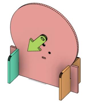
Designing the Structure
Now, young designers can begin designing the structure of the lucky roulette based on the equipment list. Let’s start by creating a parts list.
Creating the Parts List
There are three structural parts in this design, as shown in Table 1-2.
Part Number
Part Name
Quantity
Function
1
Rotating Disk
1
Display Selection Text, Fix the Motor
2
Pointer
1
Pointing Function
3
Stand
2
Support and Fix the Rotating Disk
Part Number | Part Name | Quantity | Function |
1 | Rotating Disk | 1 | Display Selection Text, Fix the Motor |
2 | Pointer | 1 | Pointing Function |
3 | Stand | 2 | Support and Fix the Rotating Disk |
Laser Modeling
The parts list is the core for guiding us to plan and design drawings systematically. We start laser modeling based on the order of the parts list.
- Drawing the Rotating Disk
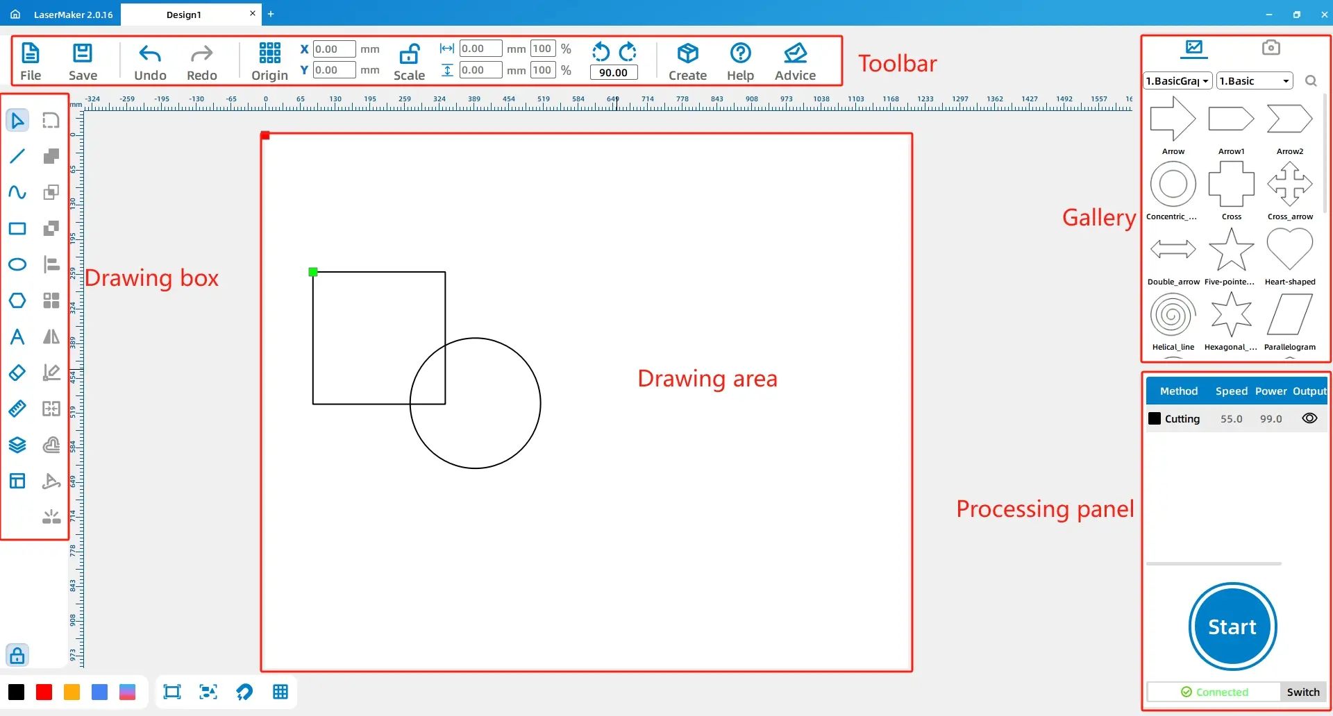
First, we open the LaserMaker software. Since it’s the first time using it, young designers need to familiarize themselves with the software’s functions. The software interface mainly consists of toolbars, drawing boxes, library panels, drawing areas, layer palettes, and processing panel functional areas, as shown in the following figure.
(1) From the [Drawing Box] on the left side, select the [Ellipse] tool, then move the mouse cursor to the drawing area. Hold down the left mouse button and drag to create a circle with a diameter of 100mm. Release the left mouse button when you see that both the width and height of the shape in the toolbar are displayed as 100mm. The [Aspect Ratio] function next to the width and height parameters settings locks the aspect ratio of the drawn shape. When you input the width or height, the software will automatically generate the corresponding height or width based on the current aspect ratio. If you need to custom set the width and height of the drawn shape, you can click this icon to unlock it.
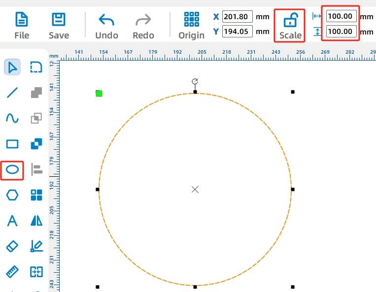
Tips: When using the [Rectangle], [Ellipse], or [Polygon] tools, you can select the desired tool with the left mouse button, hold down the Ctrl key on the keyboard, and then drag in the drawing area to create the shape. This will lock the aspect ratio of the shape to 1:1, resulting in a square, circle, or regular polygon.
Common lucky roulette designs are circular. To make it stand stably, we can use a circle combined with a rectangle for the shape of the rotating disk and add two brackets to the disk using mortise and tenon joints.
(2) From the [Drawing Box] on the left, select the [Rectangle] tool and draw a rectangle with a width of 100mm and a height of 40mm in the drawing area. Then, select the [Selection] tool from the [Drawing Box] and place the rectangle directly below the circle.
Tips: As you drag the selected shape, the software will display alignment guides to indicate the relationship between the shape and its adjacent shapes.
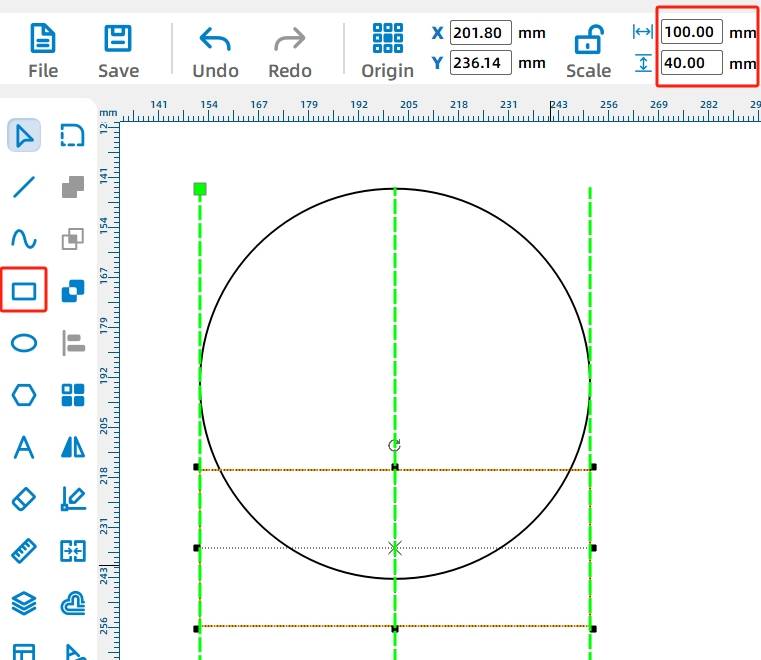
To keep the rotating disk upright, we can add two support structures underneath using mortise and tenon joints.
Tips: Mortise and tenon is a connection method using protrusions and recesses between two wooden components. The protrusion is called the tenon, and the recess is called the mortise. They fit together to form a connection.
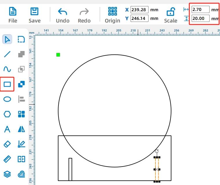
(2) Draw the mortise on the rotating disk. Select the “Rectangle” tool from the “Drawing Box” on the left and draw two rectangles with a width of 2.7mm and a height of 20mm in the drawing area. Place them below the previously drawn rectangle.
Tips: Since there is material loss during laser cutting, laser compensation needs to be set. Taking basswood as an example, it is typically set to 0.3mm. Therefore, the width of the mortise here is set to 2.7mm, not 3mm.
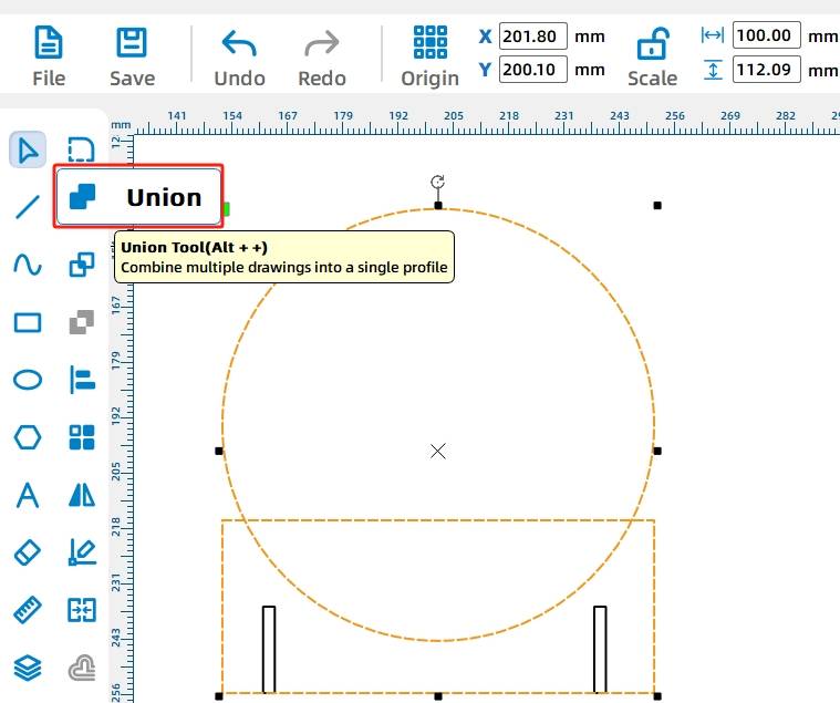
(4) You will notice that the circle and rectangle are not a single entity. Now you need to merge them. Hold down the Ctrl key, click the left mouse button to select both the circle and rectangle, and then select the “Union” tool in the “Drawing Box” to combine them into a single shape.
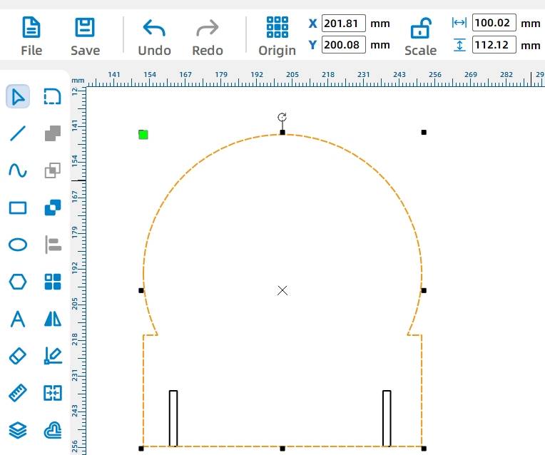
Now, the rotating disk has taken its initial shape, and we need to add a motor to make the pointer spin.
(5) In the “Library Panel” on the right side of the software, find the “Open-source Robot Hardware” option, select “TT Motor”, and drag it onto the drawing area. You can see that the motor graphic in the library is composed of multiple red or black shapes. Here, the red shapes indicate engraving during laser processing, while the black shapes indicate cutting. Engraving only leaves a mark on the material, while cutting will penetrate the material. Therefore, when a closed shape is selected for cutting, it will detach from the material during laser processing.

Clicking the left mouse button to select the motor graphic frame will reveal a “Rotate” icon above the graphic. Move the mouse to this icon, enter 270° in the pop-up input box menu, and click the “Rotate” button to confirm. The operation is as shown in the following figure.
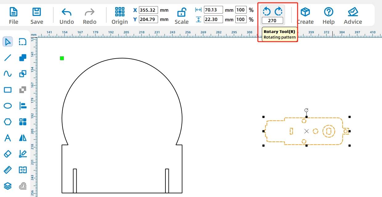
Then, continue to select the entire motor graphic by clicking on it, right-click, and select the “Group” function from the right-click menu, as shown in the following figure.
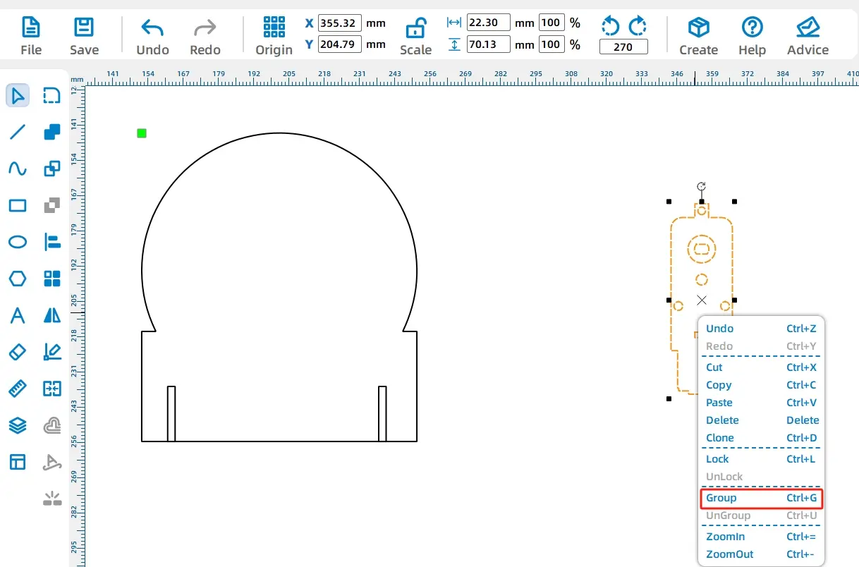
After grouping, the graphics will be treated as a single entity, and modifications to the individual graphics within the group will no longer be possible, as shown in the following figure.
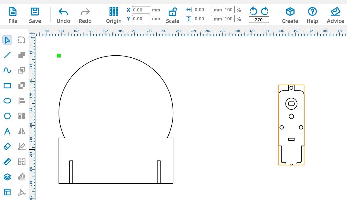
After grouping the motor, place it in the center of the rotating disk.
(6) Select the grouped motor graphic and move it to the center of the disk. Align the center of the motor shaft hole with the center of the disk as much as possible by using guide lines.
First, click the “Grid” tool in the “Drawing Box” on the left to activate the grid function, dividing the drawing area into a 10mm grid. Drag with the left mouse button to select the rotating disk graphic and align it with the grid lines.
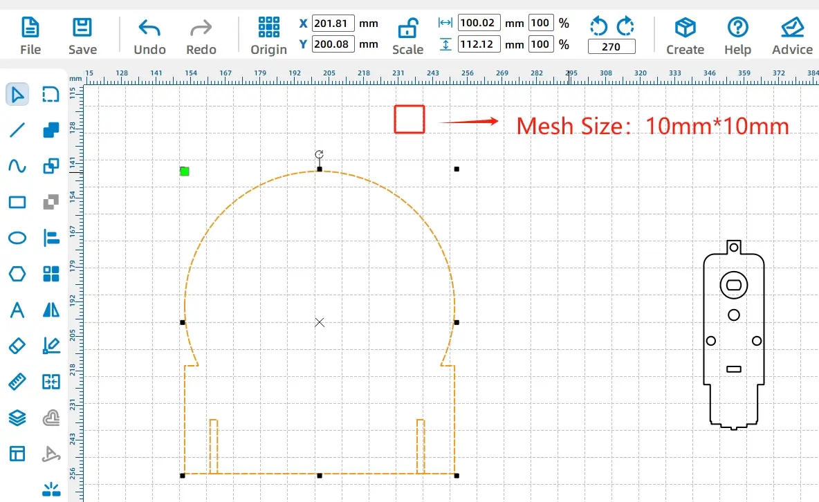
Tips: Using the Ruler
To position parts more accurately, you can also use the ruler tool for assistance.
Click the “Selection Tool” in the “Drawing Box” and move the mouse to the scale area above the drawing area. Hold down the left mouse button and drag down to create a horizontal dashed guide line. Similarly, dragging from the left scale area towards the drawing area will create a vertical guide line.
Now, to determine the center of the rotating disk, since the diameter is 100mm, simply place the guide line 50mm (or 5 small grids) from the top of the disk. Use the same method to drag out a guide line from the left side, as shown in the following figure.
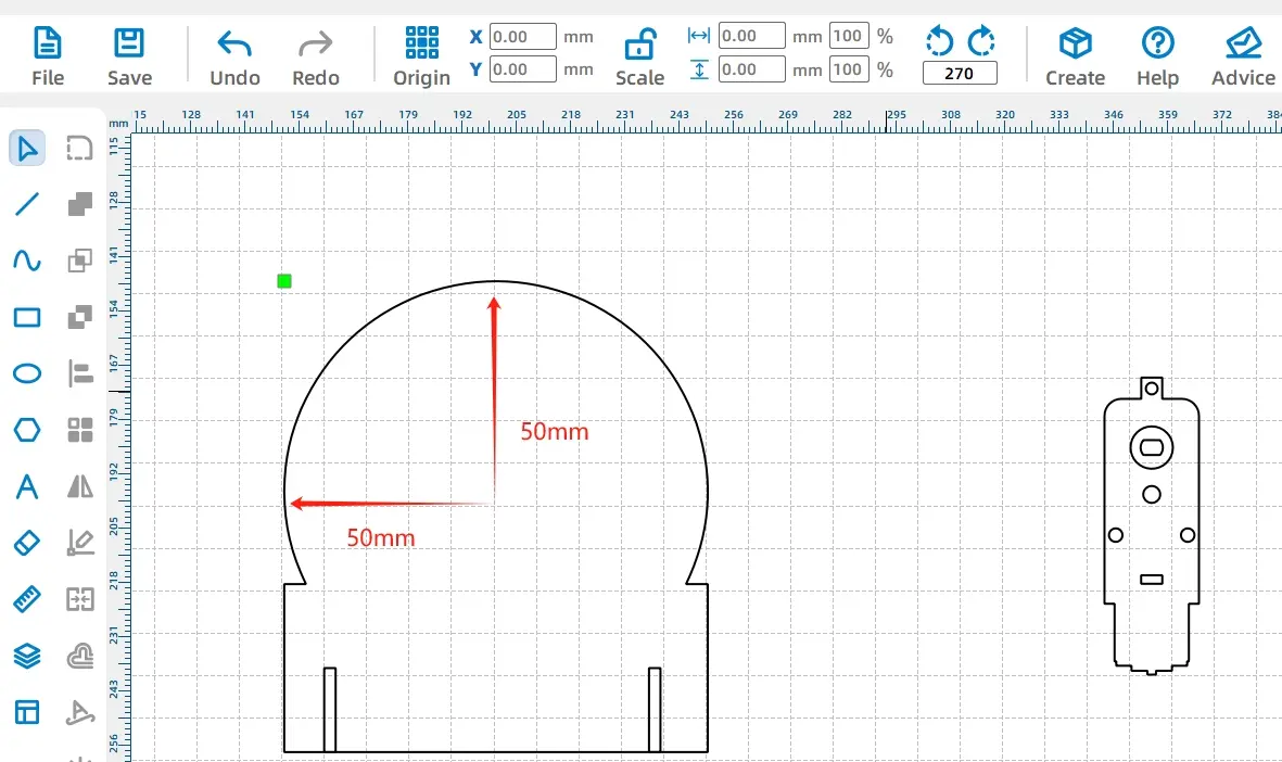
By intersecting two guide lines, you can determine the center of the rotating disk. Now, align the motor’s shaft hole with the center of the disk, as shown in the following figure.
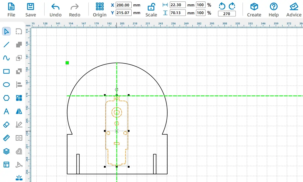
Once the motor’s position is determined, we need to add text content to the rotating disk so that visitors can identify the game they need to participate in based on the item name indicated by the pointer.
(7) Marking text on the rotating disk to add game item names. First, select the “Text” tool from the “Drawing Box” on the left, click the left mouse button where you want to place the text on the disk, and set the font type, font size, font weight, and text content in the pop-up window, as shown in the following figure.
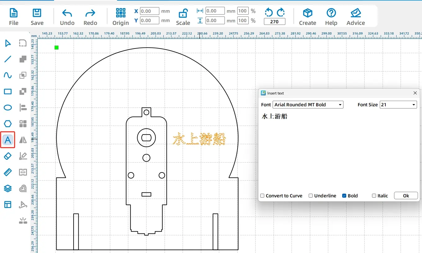
You can also set attributes like bold and italic. Once the text content is set, click “OK” to add the text to the rotating disk.
Then, to rotate the text content and enhance the aesthetics of the lucky wheel, click the “Selection” tool in the “Drawing Box,” select the text you want to rotate, click the rotation icon above the text, set the rotation angle to “-25” degrees in the pop-up input box, and finally click the “Rotate” button on the right side of the parameters.
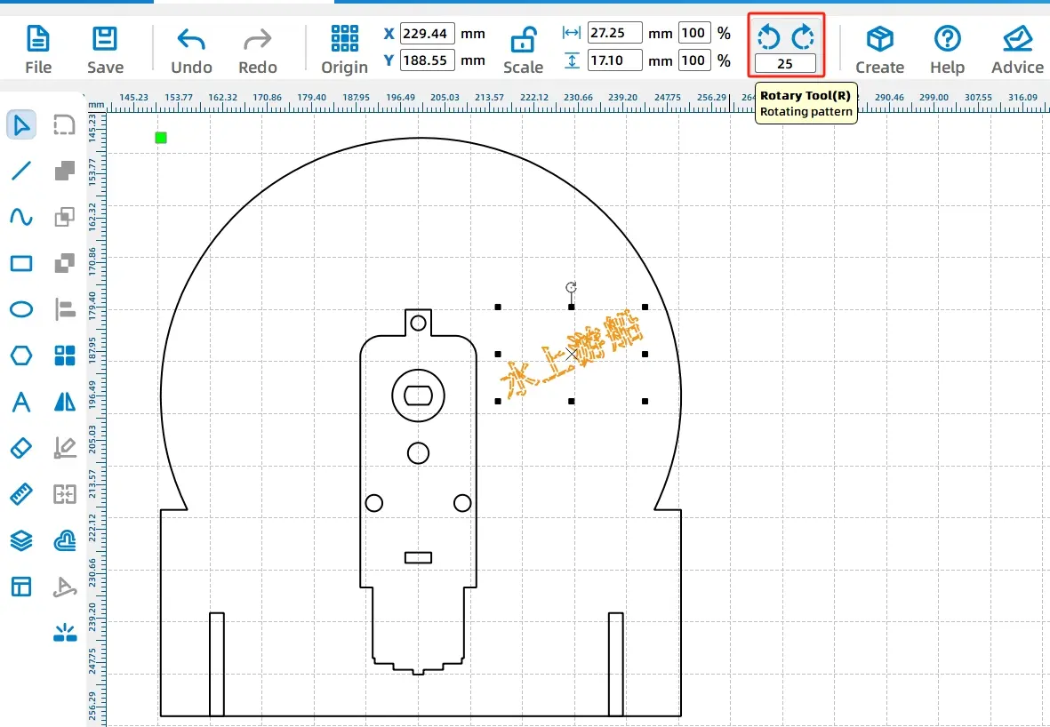
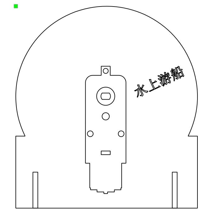
The rotated text appears as shown in the following figure.
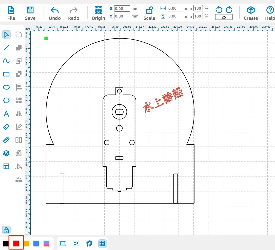
After adjusting the text position, click the red square in the “Layer Palette” at the bottom left of the software to set the cutting process for the text to “General Outlining.” Since we only want to leave a trace of the text on the rotating disk without cutting through the wood, the “General Outlining” method is required.
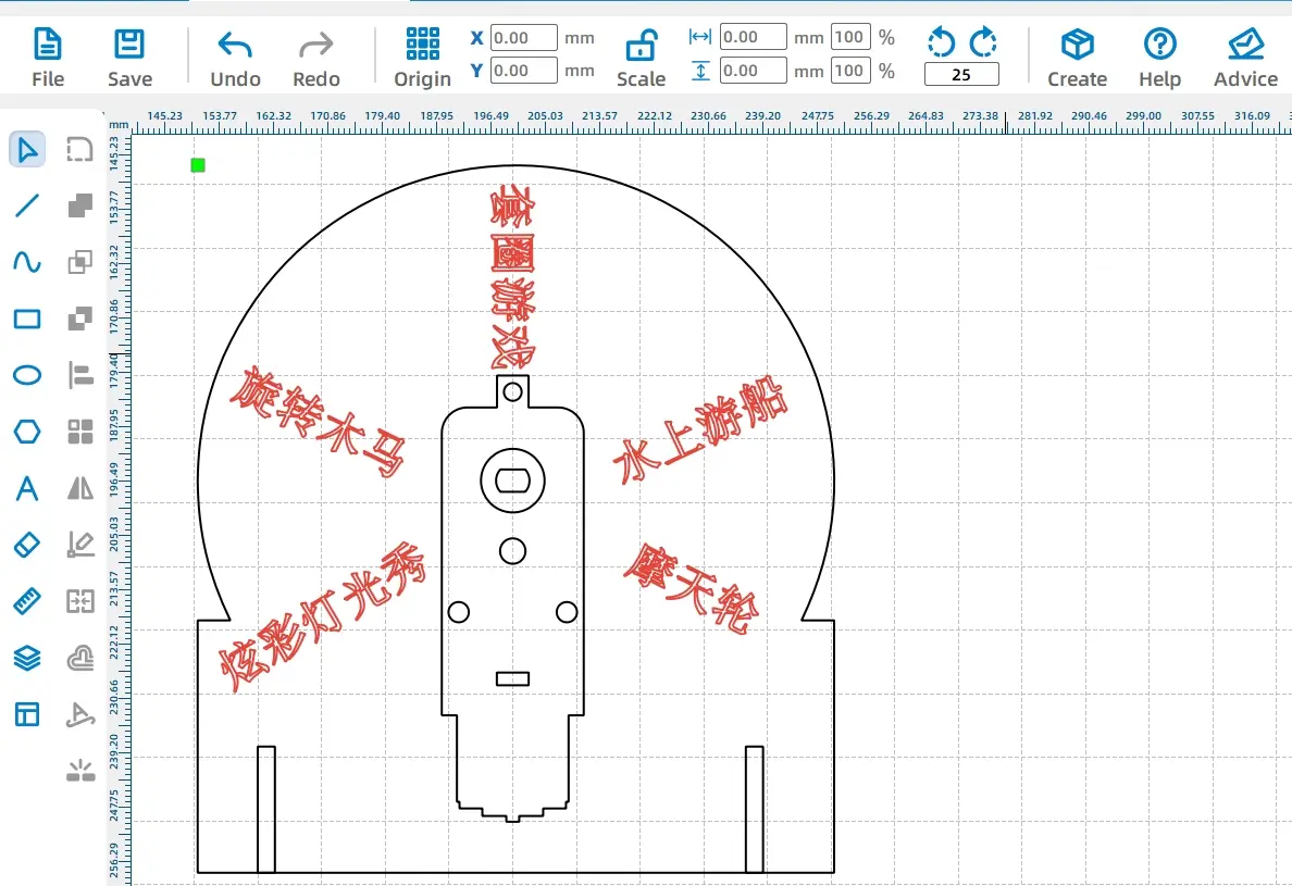
After placing the other option texts in the same manner, the design of the rotating disk is complete. The finished design with text content is shown in the following figure.
- Drawing the Pointer
With the rotating disk completed, we will now proceed to draw the pointer.
(1) Select the “Ellipse” tool from the “Drawing Box” on the left side and draw a circle with a diameter of 10mm in the drawing area. Then, in the “Library Panel” on the right side of the software, choose the “Basic Shapes” option and select the “Arrow” shape from the available graphics.
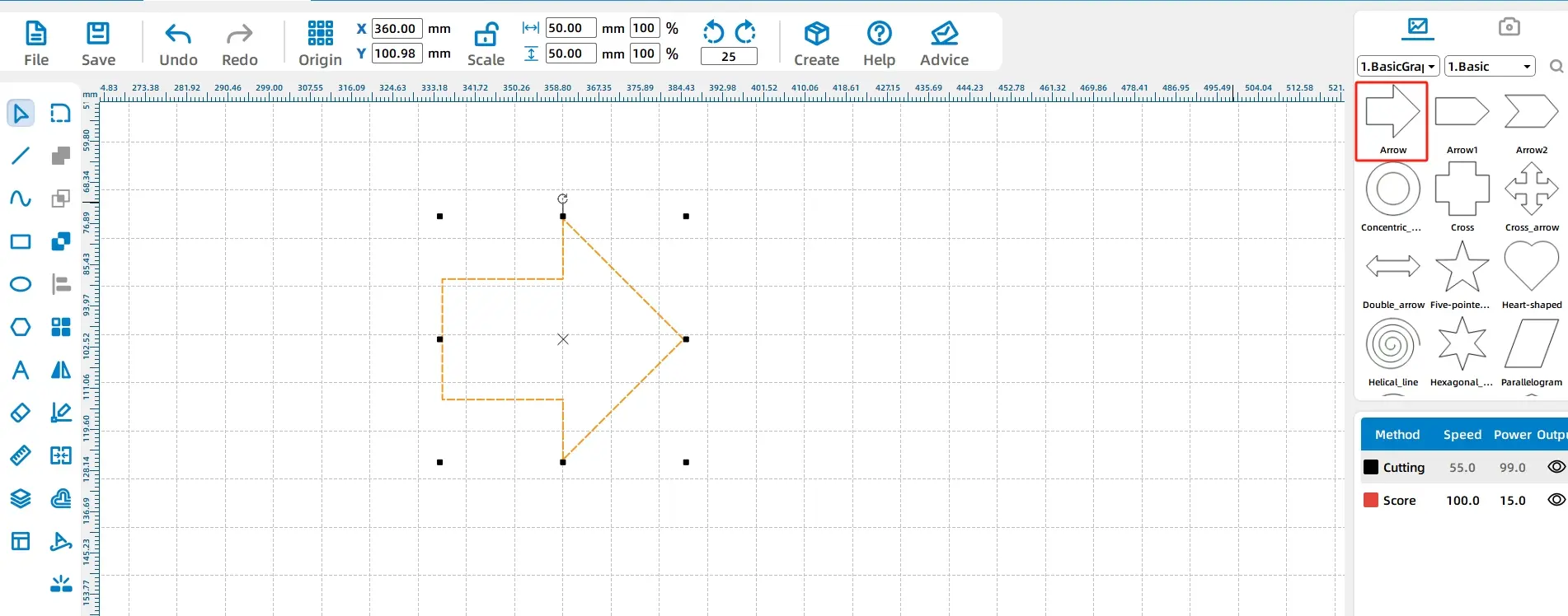
(2)Adjust the size of the arrow. Select the arrow shape with your mouse and resize it to a width of 50mm and a height of 20mm, as shown in the following figure.
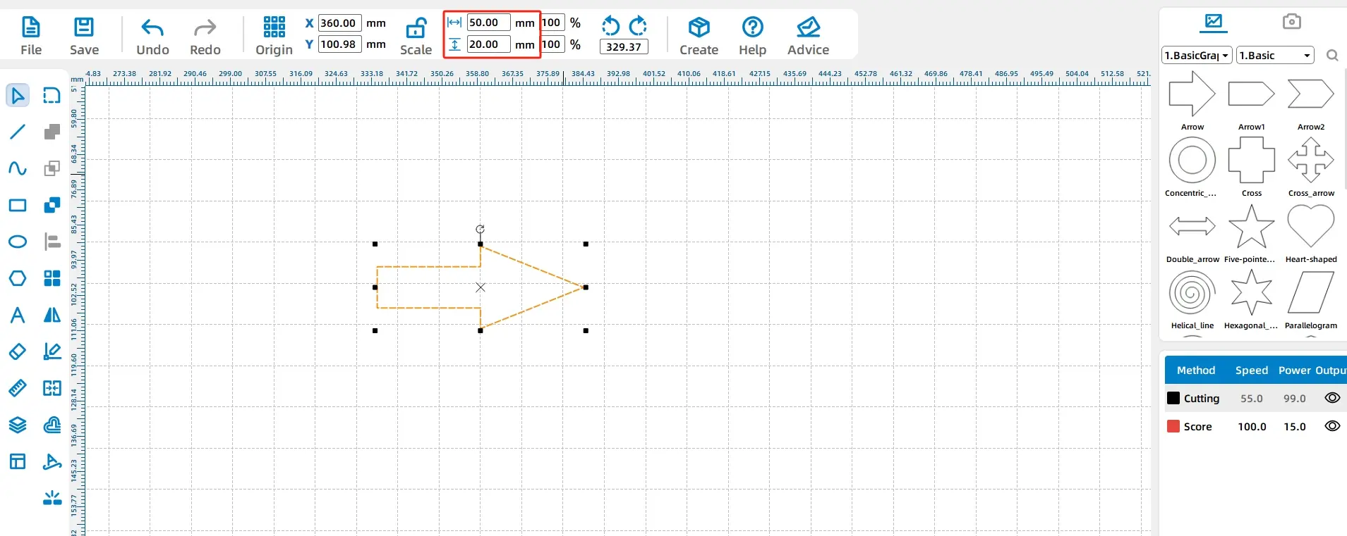
Then, use the Ellipse tool to draw a 20mm circle at the arrow’s tail, aligning half of it with the tail, as shown in the following figure.
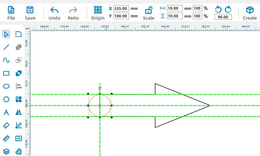
(3) As the arrow serves as the pointer, it needs to be installed on the motor shaft. Therefore, an axle hole needs to be added to the pointer.
Select “TT Hole Position” from the “Mechanical Parts” in the Library Panel on the right and place it at the center of the circle just drawn, as shown in the following figure.

(2) Next, to merge the arrow and circle, hold CTRL, select both shapes, click the “Union” tool in the “Drawing Box” on the left, and combine them. The merged arrow should not exceed the disk’s radius.
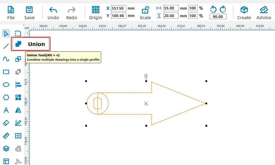
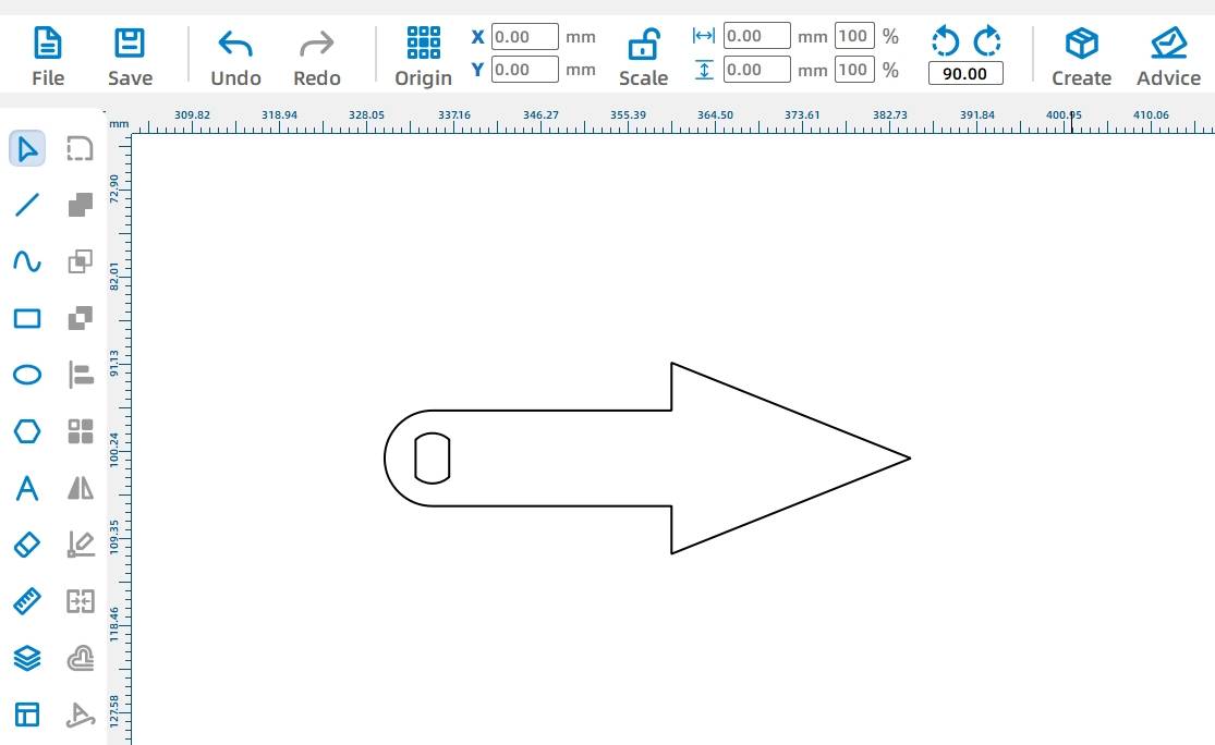
(2) After merging, the completed pointer graphic will look like in the following figure.
- Drawing the Stand
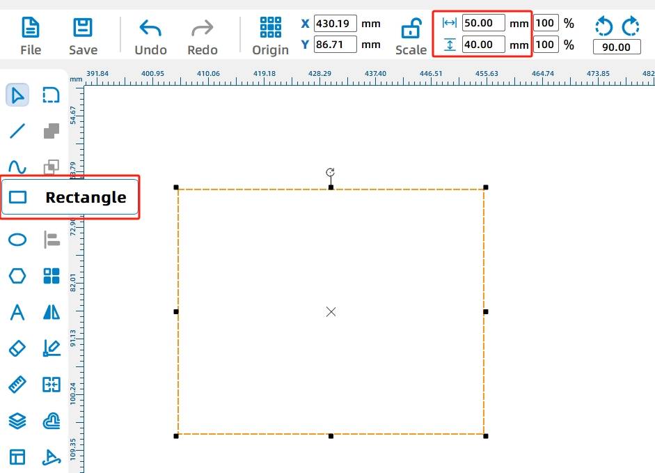
(1) Select the “Rectangle” tool from the “Drawing Box” on the left and draw a rectangle with a width of 50mm and a height of 40mm in the drawing area to serve as the stand.
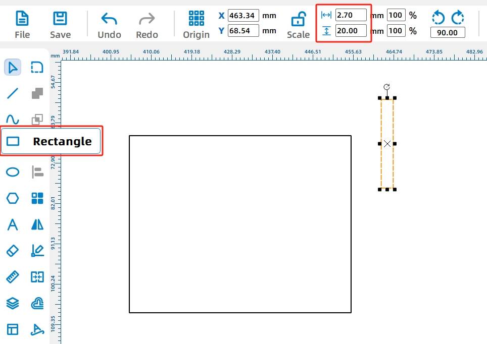
Next to the rectangular stand, draw a small rectangle with a width of 2.7mm and a height of 20mm to serve as the mortise for the stand.
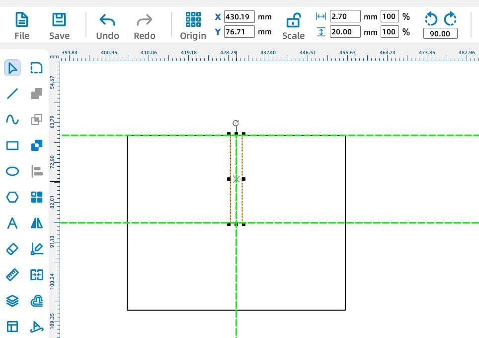
Position the mortise rectangle centered vertically and horizontally above the main stand rectangle for accurate alignment.
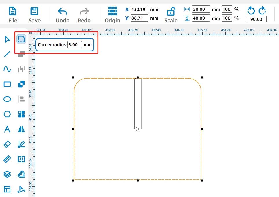
To enhance the aesthetic appeal of the stand, you can apply rounded corners. In the “Drawing Box,” select the “Round Corners” tool, set the corner radius to 5mm, and then move the mouse to the corners of the stand. Click the left mouse button to round the corners of the rectangle. The result should look like in the following figure.
(1) Next, we will duplicate the stand graphic using the copy and paste method.
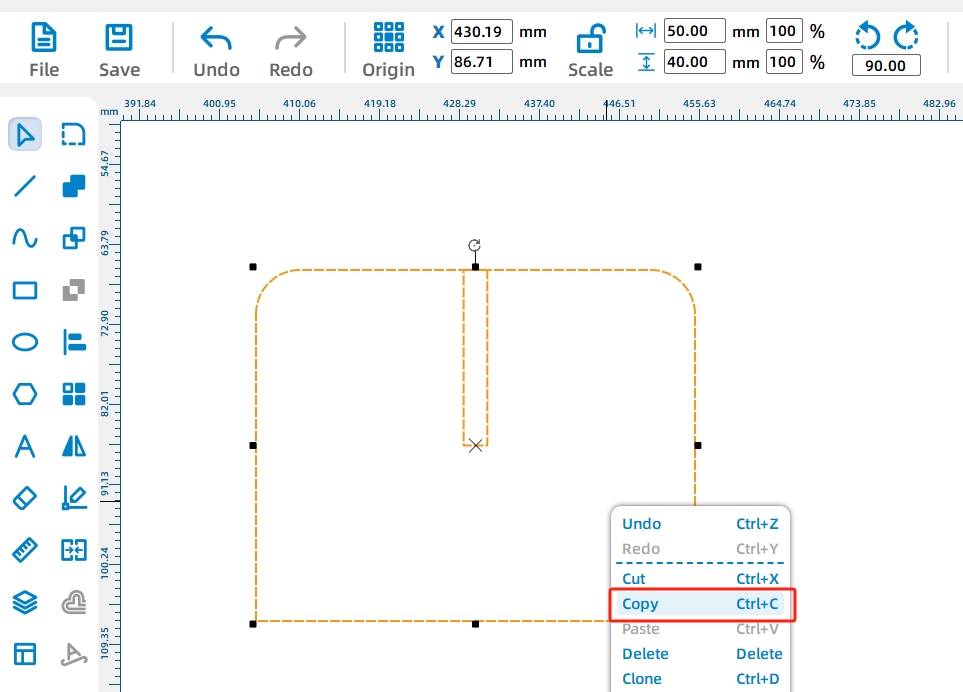
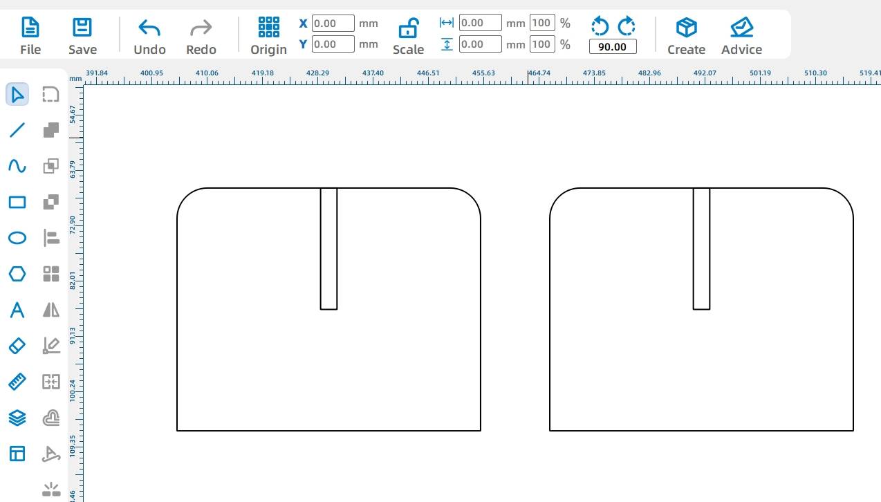
Select the stand graphic, right-click, and choose “Copy” from the pop-up menu. Then, right-click on an empty area in the drawing area and select “Paste” from the pop-up menu to obtain the second stand graphic. The result after duplication is shown in the following figure.
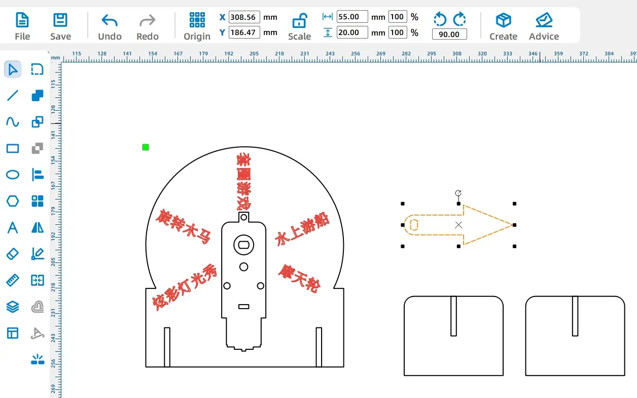
After selecting and removing the outline of the motor from the drawing, the final completed drawing is shown in the following figure.
Laser Processing
(1) Setting Parameters
The design drawing of this lucky spinner only includes two processing techniques: tracing and cutting. The text content is traced (that is, the trace is engraved), and the rest is cut (the wood board needs to be cut through). Therefore, the parameter settings for the two are different.
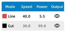
Here are the parameter settings for the two different processing techniques:
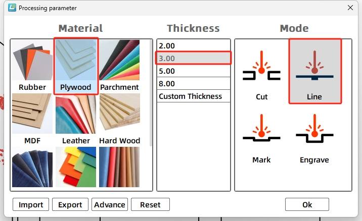
- Line
Double-click the red layer in the “Processing Panel”. For material, select 1. Basswood Plywood. For processing technique, select Line. Set the Processing Thickness to 0.10, and click OK.
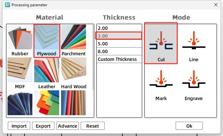
- Cut
Double-click the black layer in the “Processing Panel”. For material, select 1. Basswood Plywood. For processing technique, select Cut. Set the Processing Thickness to 3.00, and click OK.
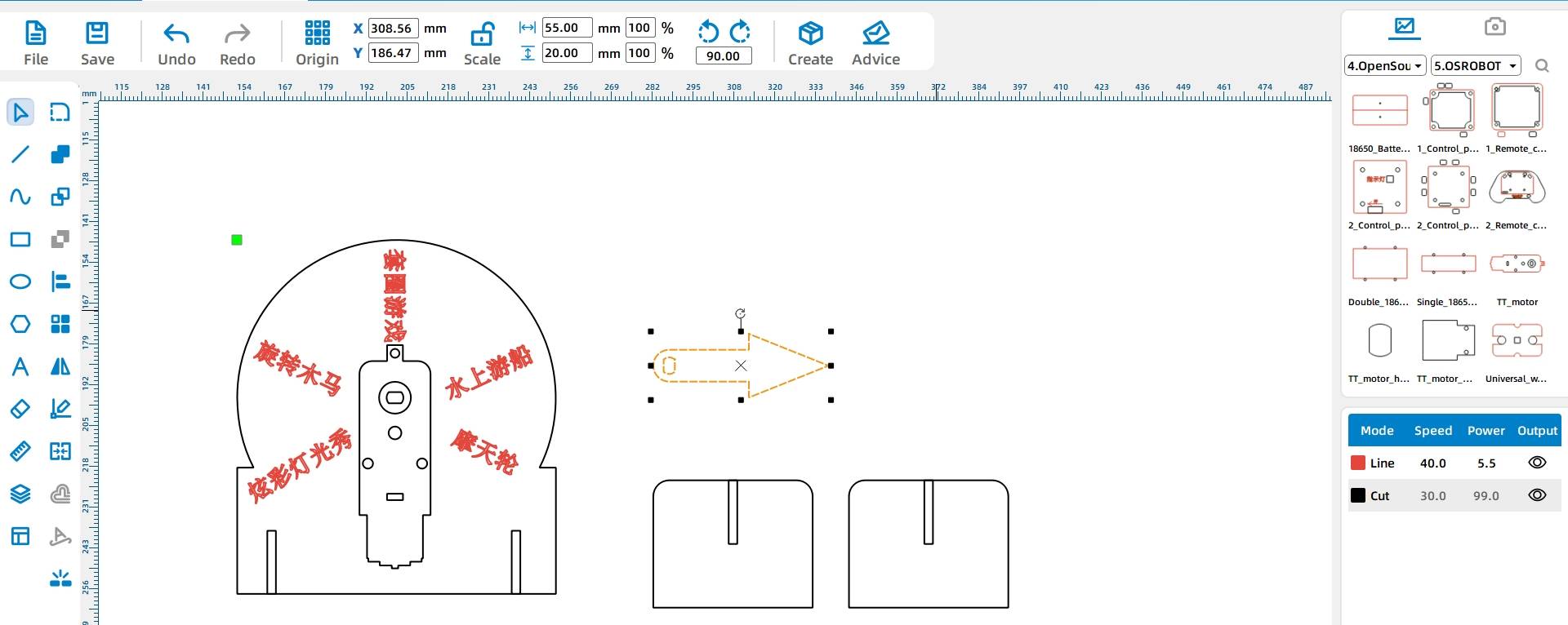
(2) Starting Fabrication
Turn on the power switch of the laser cutting machine and turn on the laser. Once the “Start Fabrication” button turns blue, click it. After the drawing is uploaded to the laser cutting machine, click the “Start” button on the “Processing Panel” and the software will send the drawing to the laser cutting machine.
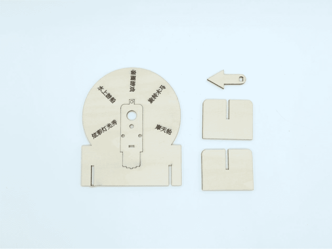
The completed physical product is shown in the following figure.
Assembly
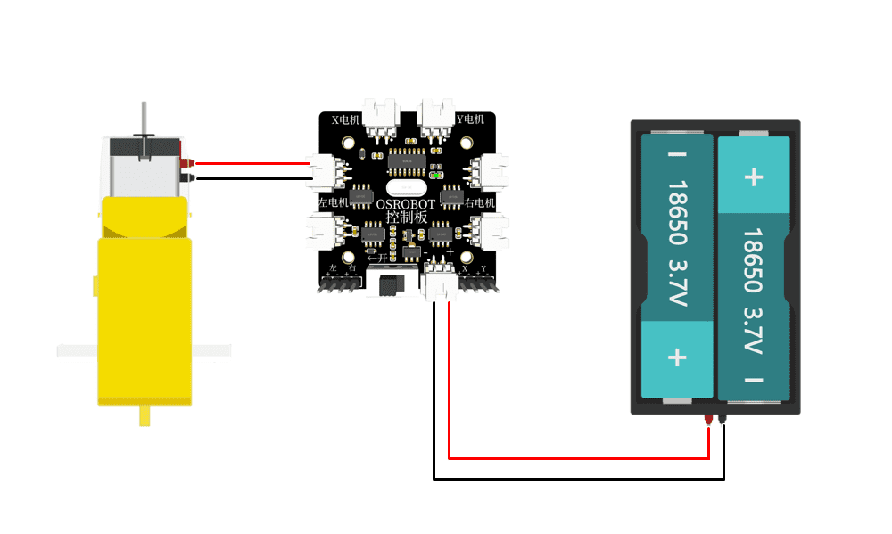
Wiring
Once the model structure is assembled, we need to connect the circuit according to the wiring diagram shown in Figure 1-39, so that the lucky spinner can start working.
Structural Assembly
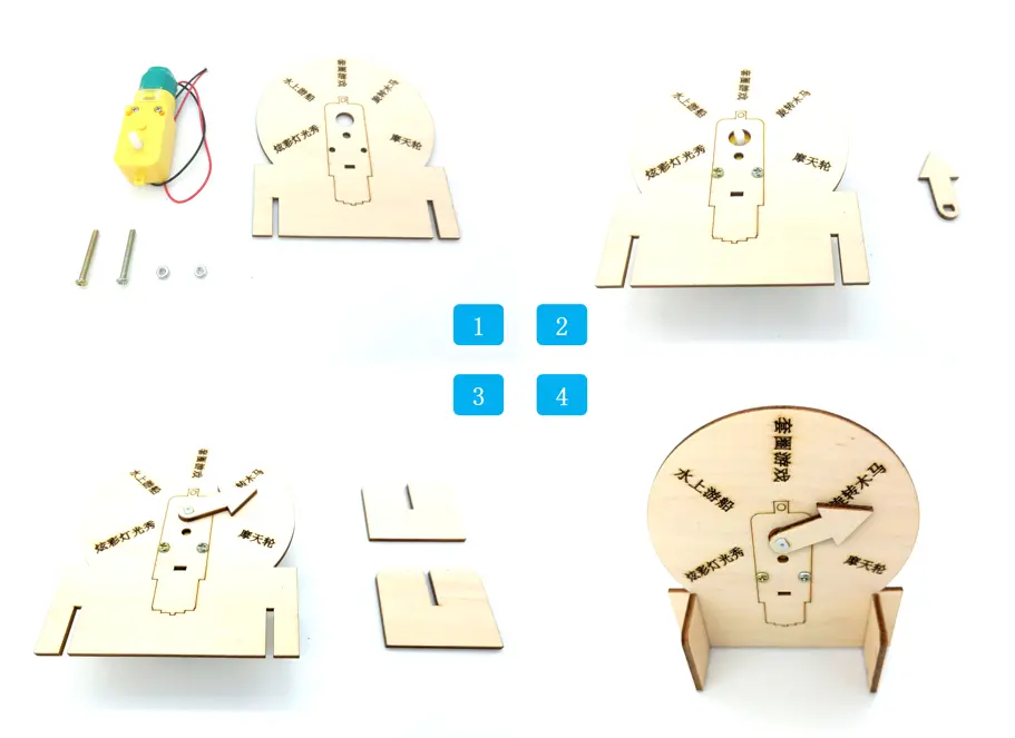
We assemble the model according to the installation steps shown in the following figure:
Step 1: Find the motor, rotating disk and hardware.
Step 2: Fix the motor on the back of the rotating disk using hardware.
Step 3: Install the pointer on the motor shaft hole and find the two support legs of the rotating disk.
Step 4: Install the support legs and the rotating disk together.
Summary
Looking back at the design process of this project, the designers first learned about the mortise and tenon joint, which connects two structural components through concave and convex combinations. They also became familiar with the use of drawing tools in the “Drawing Box” of LaserMaker software, such as “Rectangle,” “Ellipse,” and “Rounded Corner.” They learned about adding shapes to the library, rotating shapes, and other functional operations. They gained an understanding of common laser cutting processes, thus experiencing the entire process from design to physical creation.
Although the lucky spin wheel is complete, the challenge for the designers in the laser creation playground has just begun. Let’s wait and see what comes next.

Thought Expansion
The text for the amusement items on this lucky spin wheel is not modifiable. If we want to change the game’s text content, we would have to re-engrave another wheel, which would inevitably waste materials. Is there an alternative solution? Let’s put our heads together with the designers and design even more creative works.
Browse Thunder Laser
Bolt >



.png) International
International
 United States
 Brasil
 Canada
 Costa Rica
 Česká
Česká
 Ελλάδα
 Polska
 Ireland
 Portugal
 Lietuva
 Россия
 Deutschland
 Britain
 Україна
 France
 Sverige
 Italia
 Norway
 Denmark
 Romania
 한국
한국
 中国
中国
 ประเทศไทย
 中国香港
中国香港
 Israel
 中國臺灣
中國臺灣
 India
India
 پاکستان
 پශ්රී ලංකා
 ジャパン
ジャパン
 Australia
 New Zealand
 South Africa