(1) Master the comprehensive application method of “Rectangle tool”, “line segment tool”, “rectangular array tool” and “text tool”.
(2) Master the operation method of line dislocation to form a graphic array.
Thinking training
Design thinking
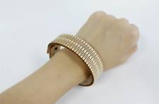
(1) Understand the design ideas and operation methods of reducing material density and forming bendable surfaces by hollowing out of hard materials.
(2) Foresee which parts of which objects can be achieved by hollow cutting to form a curved surface.
(3) Master the design method of cover and back cover hinge buckle.
Computational thinking
(1) Master the calculation method of cutout density and cutout format of graphic array cutting.
(2) Master the design and distribution calculation methods of rectangular array and replicated graphics.
Engineering thinking
(1) The cutting design and bending toughness effect were tested according to the linear graph array density.
(2) Conduct hollow bending experiments after cutting and reducing different materials, and understand the influence of different hollow density and material brittleness on practicability.
Social responsibility and moral literacy
(1) The content of the works is healthy and civilized, pay attention to the protection of information security, and comply with information laws and regulations, information ethics and moral norms.
(2) In practice, you can imitate others’ works in style, and you must do improved innovation when creating.
2. Application scenario
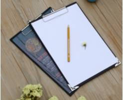
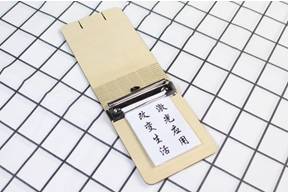
In restaurants, we often see waiters with sticky notes in their hands, taking notes on what customers have ordered. In life, we often need to record some plans and urgent things, as shown in the following figure. As the saying goes, a good memory is not as good as a bad pen, with a sticky note holder, can be easy to record, always remind yourself. Think about how you can design the shell of a sticky note holder in LaserMaker to create a personalized sticky note holder.
3. Project analysis
(1) The shape of the piece: the cover of the note clip or binder is folded by a piece of workpiece material into the upper and lower bottom surface. The folding position can be bent, generally made of soft leather, which is conducive to bending. If it is hard, use customized mold bending surface treatment, or cut the bottom surface, perforated, and fixed with string. Using a piece of wood to make the cover and back cover with a laser cutting machine, it is necessary to make the folding position into a flexible curved surface.
(2) Modeling method: Using line tools and array tools, draw and copy to form a discontinuous line array, displace the line array, cut the cutting bit and the connecting bit evenly, calculate and control the cutting format, and repeatedly experiment to achieve the appropriate width. The hinge buckle is connected by cutting a strip clip.
(3) Product size: Measure the size of the cover and back cover according to the size of the note paper and the size of the paper note page; The surface width is calculated according to the bending thickness, and its feasibility is tested.
(4) Splicing method: card buckle method.
(5) Material selection: basswood plywood, corrugated paper.
(6) Process effect: The main use of “shallow carving” and “cutting” process, in the drawing to consider the cover, back cover engraving you like the text, pattern pattern and other personalized design.
4. Modeling process
1.Research and hand-drawn design
Measure
By searching the Internet or observing the physical sticky notes, what size do you decide to draw the sticky notes? Does this size fit your needs? Please fill in the form below according to your design.
Data recording unit: mm
Length:
Width:
Flat clip length:
Hole diameter:
Paint
Based on your measurements and design elements, draw a design sketch of the note holder inside the box.
2.Software drawing
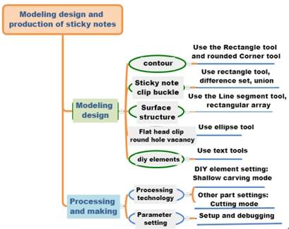
After the structural analysis of the note holder, we can complete the drawing of the graph through 6 steps.
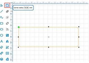
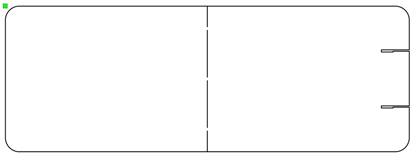
Use the “Rectangle Tool” and “Rounded Corner tool” to draw the outline of the sticky note holder.
Click the Rectangle Tool and draw a rectangle with a width of 290mm and a height of 104mm in the blank area. Click “Rounded Corner Tool”, enter the radius “10” in the pop-up “Rounded Corner Tool” dialog box, move the mouse pointer to the four corners of the rectangle, and round them respectively to complete the drawing of the rounded corner rectangle, as shown in the following figure.
(2) Use the “Rectangle Tool”, “Union Tool” and “Difference set tool” to draw the sticky note clip buckle.
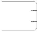
Click “Rectangle Tool”, draw a rectangle 20mm wide and 1mm high in the blank area of the drawing area, draw another rectangle 8mm wide and 1.5mm high, move this rectangle to coincide with the other rectangle, select the two rectangles at the same time, click “Merge tool”, merge the two rectangles into one graph. As shown in the following figure.
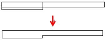
Move the merged graph to the right center of the rounded rectangle, modify its Y wheelbase distance, reduce its value by 20mm, click, the position of the graph will change; Similarly, copy this figure, move it to the right center of the rounded rectangle, increase its Y wheelbase by 20mm, and the figure will shift, as shown in the following figure.
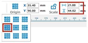
As shown in the following figure, select the graph of the sticky note clip buckle at the same time, change the “object origin” to the left, change the width to “21”, click the graph, and the graph will expand to the right.
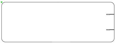
Select the graphics one by one and click “Difference Set Tool” to open slots on the rounded rectangle, as shown in the following figure.
(3) Use “Line Segment Tool” and “Rectangular array” to draw the surface structure
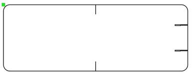
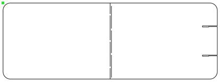
Click Line Segment Tool to draw a line segment inside the rounded rectangle, change its height to 15mm, and move it to the top middle of the rounded rectangle. Copy the line segment and align it to the bottom center, as shown in the following figure.
Click Line Segment Tool, draw a line segment with a height of 34mm in the rounded rectangle, and move it to align with the previous line segment. Reduce the value of the Y-axis by 2mm. Then move the line segment down by 2mm. Copy the line segment and use the same method to move the line segment down 2mm. As shown in the following figure.
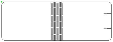
Click Line Segment Tool, draw a line segment with a height of 31mm, click Rectangular Array, enter 1 in Horizontal Number, 3 in Vertical Number, and 2.5 in Vertical Spacing, and click OK. Select the 3 line segments and move them to coincide with the 4 line segments in the above figure. Increase the value of the X-axis by 1.68mm, then the 3 line segments will move 1.68mm to the right, as shown in the following figure.
Select all line segments, click Rectangular Array, enter 10 in Horizontal Number, 1 in Vertical Number, and 1.5 in Horizontal space, and click OK to finish drawing the surface structure. When you have finished drawing, move it to the middle of the rounded rectangle, as shown in the following figure.
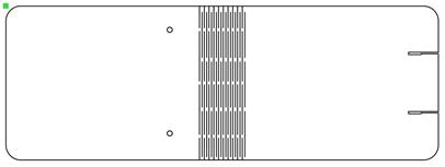
(4) Use the “Oval tool” to draw the hole position of the flat head clip round hole
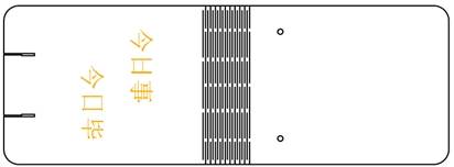
Click the Oval Tool, draw a 3.5mm diameter circle in the rounded rectangle, align it to the center of the first line segment on the right, reduce the X-axis value by 20mm, and the circle will move 20mm to the left. Duplicate the circle, move the two circles to coincide, increase the Y-axis value by 70mm, and one circle will move down by 70mm so that the distance between the two circles is 70mm. Select two circles and move them so that they are centered up and down, as shown in the following figure.
(5) Use the Text Tool to add text
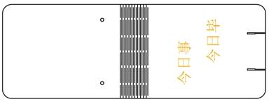
Select the graph, click “Rotate”, rotate it by 90°, click “Text Tool”, double click in the blank area of the drawing area, enter “Do today” and “Finish today” in the pop-up “Draw Text” dialog box, set the line height to 15mm, and move it to the middle position below the note clip, as shown in the following figure.
(3)Process pattern design
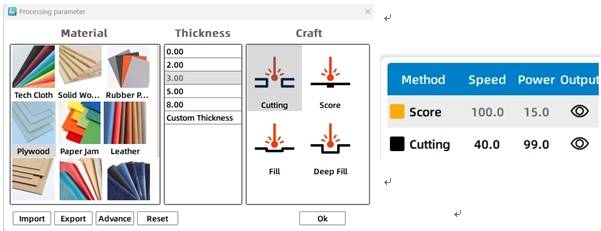
As shown in the following figure, select the text object, set to “yellow light carving” process layer, double-click the layer, pop up the “Processing parameters” dialog box, set the processing material to basswood plywood, process to shallow carving, processing thickness to 0.1mm.
Select the other objects in the sticky note folder, double-click the process layer, pop up the “Processing parameters” dialog box, set the processing material to basswood plywood, the process to cut, and the processing thickness to 3mm.
Finally, adjust the sequence of processing layers as follows: shallow carving → cutting, as shown in the following figure.
Thinking and debugging
(1) Adjust the degree of dislocation of the lines, and experiment the influence of the layout of the lines on the bending effect of the surface.
(2) Delete some lines, which is equivalent to opening the spacing of lines, and experiment the influence of line density on the bending effect of the surface.
(3) Explore other lines or graphic arrays and try their processing effects through experiments.
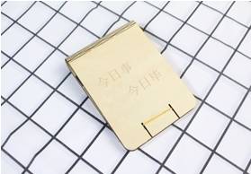
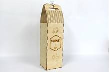
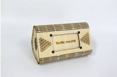
5.Display of finished products
The finished product is shown in the following figure.
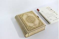
6.Extension exercise
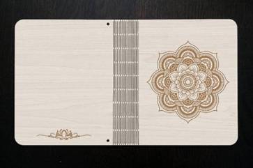
Notebook is one of the important learning tools, an interesting and creative notebook, can increase the fun of learning, so that learning is no longer boring. Refer to Figure 5.135 and try drawing a wooden laptop shell using LaserMaker.
7.Work appreciation
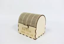
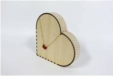
The following figure shows various curved structure works of LaserBlock open source community for your reference and appreciation.

.png "laser cutter Globle") International
International
 United States
 Brasil
 Canada
 Costa Rica
 Mexico
 Česká
Česká
 Romania
 Polska
 Ireland
 Italia
 Lietuva
 Россия
 Deutschland
 Britain
 Україна
 France
 Sverige
 Norway
 Denmark
 Ελλάδα
 Portugal
 한국
한국
 中国
中国
 中国香港
中国香港
 Israel
 中國臺灣
中國臺灣
 ジャパン
ジャパン India
India
 پاکستان
 پශ්රී ලංකා
 ประเทศไทย
 Australia
 New Zealand
 South Africa