Dear designers, the amusement park manager on Planet M hopes to distribute a souvenir medal to every visitor at the final stop of their amusement park. Manual distribution one by one seems cumbersome, so the designers are considering how to design an automatic medal dispenser. Now, let’s follow the designers and create a souvenir medal dispenser together.
Determining the Design Scheme
Analyzing the Work
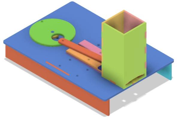
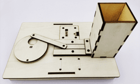
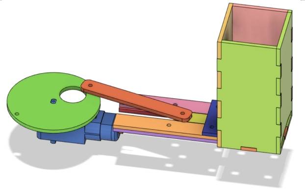
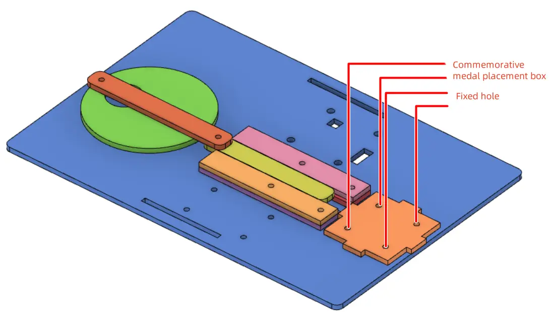
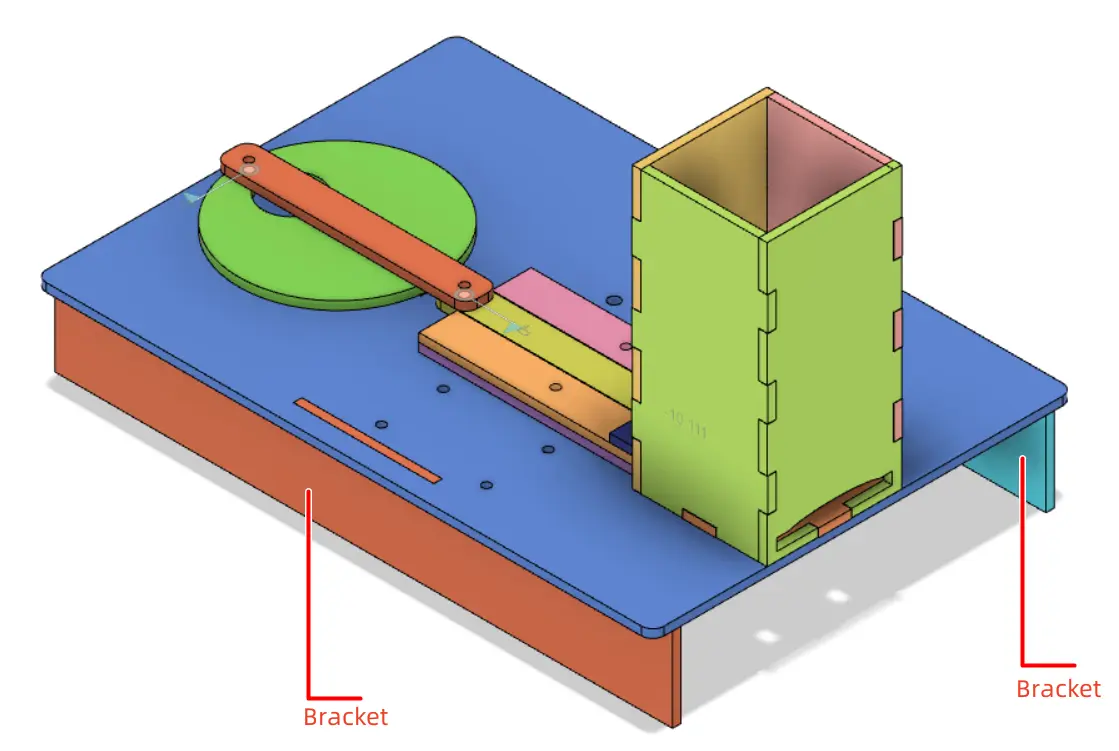
Dear designers, to realize the design of the souvenir medal dispenser, we must first design the dispensing item – the souvenir medal. Then, we need to consider its core function – automatic medal dispensing. Since we are using a TT motor for power, we need to convert circular motion into linear reciprocating motion. In addition to the stop lever used in the amusement park billboard project, a crank-slider mechanism can also achieve a similar function. In this project, we can utilize this characteristic of the crank-slider mechanism to realize the function of pushing out the souvenir medals. With the addition of a power unit, we can achieve automatic medal dispensing. Finally, design a medal holder with an exit slot to store the medals. Combine all three components onto a base, and the basic components of the souvenir medal dispenser are planned out, as shown in the following figure.
Tip:
A crank-slider mechanism is a planar linkage mechanism that utilizes a crank and a slider to achieve the conversion between rotation and translation. As shown in the figure below, this mechanism is commonly found in reciprocating piston engines in our daily lives, as well as in compressors and punches used in industrial production.
Materials List
After determining the basic components of the souvenir medal dispenser, we can proceed to the Maker Factory to select appropriate materials for processing and assembly to achieve the desired functionality. The souvenir medals, crank-slider mechanism, medal holder, and base of the dispenser can all be made from basswood plywood. We’ll use a TT motor as the power unit, opting for a high-ratio TT motor (ratio 1:220) to reduce the rotational speed. A single 18650 battery will be used to power the device (further reducing the speed). The core controller will be our Maker Factory’s magical OSROBOT remote control and receiver. Based on this, the materials list can be finalized as follows:
No.
Name
Quantity
1
2.4G Remote Control (with Battery)
1
2
2.4G Receiver
1
3
TT Motor (1:220 Gear Ratio)
1
4
18650 Battery (with Wire)
2
5
Basswood Plywood (40cm60cm3mm)
1
6
M3 Flat Head Screws, M3 Nuts, M3*6 Single-Pass Copper Standoffs
Several
7
R3080 Nylon Rivets
2
8
Cable Ties
2
Structural Design of the Project
The key to the success of the souvenir medal dispenser lies in its structural design. Next comes the most crucial part of this project – designing the structure of the souvenir medal dispenser.
Creating a Parts List
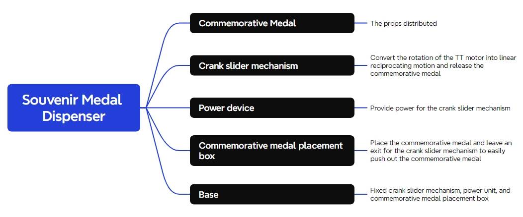
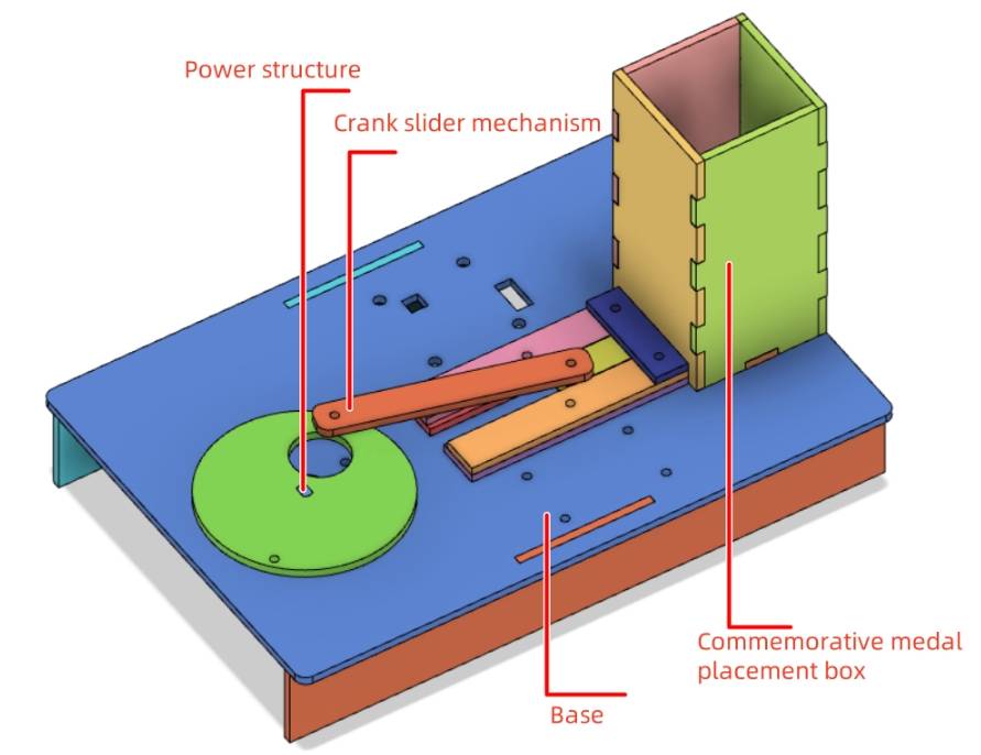
By analyzing the structure of the souvenir medal dispenser and combining it with the materials list, we need to determine the parts list for this project. The structural components designed for this project consist of five parts in total.
Part No.
Part Name
Quantity
Function
1
Souvenir Medal
10
Item to be dispensed
2
Crank-Slider Mechanism
1
To push out the souvenir medals
3
Power Unit
1
To provide power to the crank-slider mechanism
4
Medal Holder
1
To store the souvenir medals
5
Base
1
To secure and stabilize other components
Laser Modeling
After determining the parts list for this project, we can proceed with laser modeling based on the parts list.
1.Designing the Souvenir Medal
Common souvenir medals are round, so we’ll design ours as a circle. The LaserMaker software provides a “Badge/Stamp” function in the “Creation” tool of the toolbar.
(1) Main Design of the Souvenir Medal
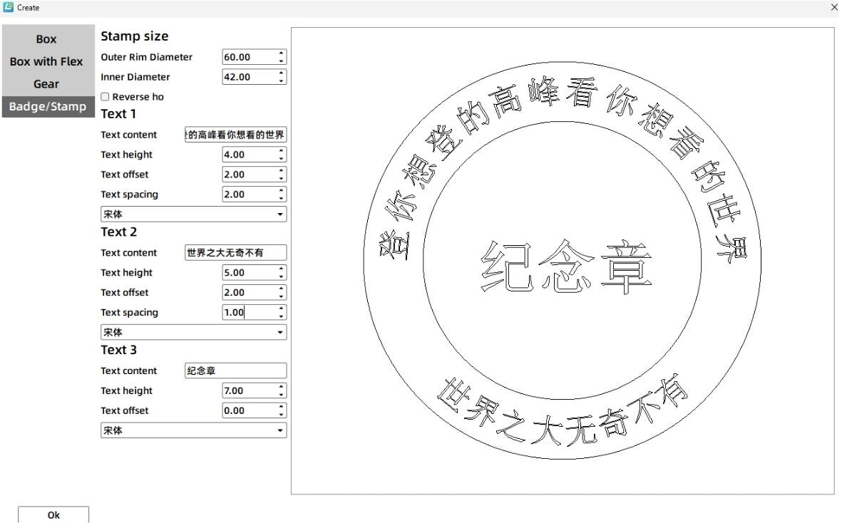
Open LaserMaker, click “Creation” in the toolbar, select “Badge/Stamp”, and start modifying the parameters.
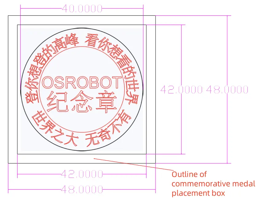
Set outer diameter to 60mm and inner diameter to 42mm.
Text 1: “Climb the peaks you want, see the world you dream of” – height 4mm, offset 2mm, gap 1mm, default font.
Text 2: “The world is vast, filled with wonders” – height 4mm, offset 2mm, gap 1mm, default font.
Text 3: Scroll down to display the full settings for Text 3. Set content to “Souvenir Medal” – height 7mm, offset 6mm, default font.
Click “OK” to obtain the initial design of the souvenir medal.
(2) Adjusting the Medal and Adding Text
The 60mm diameter medal is relatively large, so we can further reduce its size. Using the “Selection Tool” in the “Toolbox”, hold down the left mouse button and drag to select the medal graphic. While maintaining the aspect ratio, set the medal size to 40mm wide by 40mm tall.
Click the “Text Tool” in the “Toolbox” and double-click above the “Souvenir Medal” text. After the “Draw Text” window appears, set the font to default, font size to Xiao Wuhao, and input “OSROBOT”. Click “OK” to display “OSROBOT” above the “Souvenir Medal” text. Use the “Selection Tool” to select the “OSROBOT” text, drag it to align horizontally with the medal, and maintain a suitable gap from the “Souvenir Medal” text.
To ensure the outer circle of the medal is cut through during processing to create a round badge, we can change the layer of the outer circle to black, indicating a cutting process. Set the inner graphics to red, indicating a tracing process, so that only scratches remain during processing without cutting through. Now, a round souvenir medal design is complete.
Tips:
Why not set the dimensions directly in “Badge/Stamp” instead of resizing it later? Using the default 60mm x 60mm size and scaling down preserves text parameters, simplifying the design process.
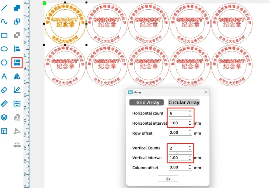
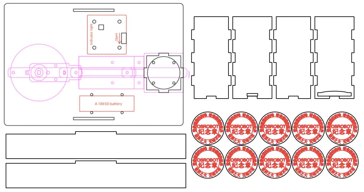
(3) Duplicating the Medal Design in a Rectangular Array
To ensure enough medals for everyone, we can duplicate the design using a rectangular array. Select the medal, click “Rectangular Array” in the toolbar, and set parameters: 5 horizontally with 1mm spacing, 2 vertically with 1mm spacing. Click OK to obtain a drawing for 10 medals.
Drawing a Crank-Slider Mechanism
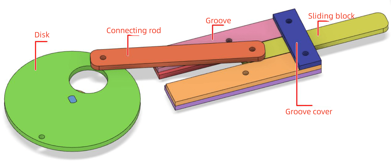
The crank-slider mechanism is the core structure of the medal dispenser, responsible for converting the rotational motion of the TT motor into a reciprocating linear motion of the slider. Here, we can design a crank-slider mechanism composed of a disc (equivalent to the crank), connecting rod, slider, and groove (to restrict the slider’s movement trajectory).
(1) Adjusting the “TT Motor” Graphic
The crank-slider mechanism is powered by a TT motor, which drives the rotation of the disc (crank). Therefore, during the drawing process, the position of the disc can be determined based on the location of the TT motor shaft.
Select the “TT Motor” graphic from the “Open-Source Robot” option in the LaserMaker library and drag it onto the canvas.
The shaft of the TT motor connects to the disc. Observing the orientation of the TT motor in the image below, we can see that the shaft is located on the left side, while the “TT Motor” graphic in the library has the shaft on the right side. Therefore, we need to adjust the “TT Motor” graphic accordingly.
Tips:
Why is the shaft of the TT motor placed on the left?
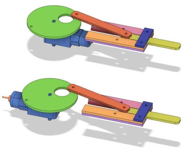
As shown in the comparison of the following figures, when the shaft of the TT motor is on the left, the entire motor is positioned towards the right, resulting in significant space savings.
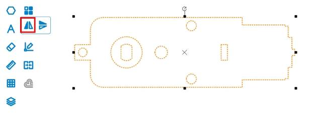
Press and hold the left mouse button to drag and select the “TT Motor” graphic. Click the “Horizontal Flip” tool in the “Drawing Toolbox” to flip it left to right. Check the dimensions of the TT motor in the Dimension box. Select the TT motor graphics and right-click, choosing the grouping function to combine them. This ensures that during subsequent operations, no accidental movements will cause the graphics within the TT motor to shift position.
(2) Drawing the Disc (Crank)
To ensure smoother operation of the crank-slider mechanism, in the above design, we have chosen a disc shape to replace the elongated crank.
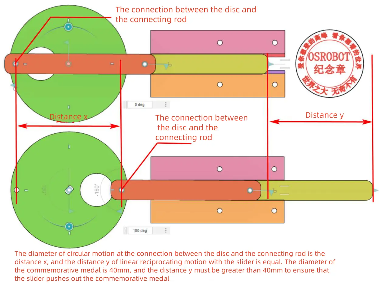
To draw the disc, the first step is to determine its diameter. Since the TT motor shaft rotates the disc, and the disc’s rotation drives the connecting rod and slider, the diameter of the circular motion at the connection point between the disc and the connecting rod determines the reciprocating motion distance (stroke) of the slider, which also determines the distance for moving the commemorative coin. Given that the commemorative coin has a diameter of 40mm, the diameter of the circular motion at the connection point between the disc and the connecting rod must be greater than 40mm. To leave room for subsequent design adjustments, we can set the disc’s diameter a bit larger, and in this case, we choose 70mm.
Once the disc diameter is determined, we can start drawing. Using the “Ellipse Tool” in the “Drawing Toolbox,” draw a circle with a diameter of 70mm on the canvas as the outline of the disc.
Next, we need to determine the assembly position of the disc and the TT motor. Since the “TT Motor” graphic has a circle that aligns with the center of the shaft, we can use the “Ellipse Tool” in the “Drawing Toolbox” to draw another circle with a diameter of 10mm for positioning assistance. Select both the 70mm and 10mm circles, then use the “Align” tool in the “Drawing Toolbox” with the “Horizontal Center Alignment” and “Vertical Center Alignment” functions to align the two circles, placing the smaller circle in the center of the larger one, forming a set of concentric circles. Then, select both circles, right-click, and choose the grouping function to combine them. Drag the concentric circles with the mouse until the 10mm circle overlaps with the 10mm circle on the TT motor. This way, the assembly position of the disc and the TT motor is determined.
Tips:
Can’t we directly align the disc with the TT motor using the alignment tool?
No, we cannot. In the Lasermaker software, the alignment tool defaults to aligning smaller graphics to larger ones. Since the disc is significantly larger than the TT motor shaft, using the “Align” tool to align them is not appropriate. The TT motor drawing has a pre-reserved hole with a diameter of 10mm for the TT motor shaft to pass through, and it is aligned with the center of the TT motor shaft. Therefore, aligning the center of the disc with this 10mm circle will automatically align it with the center of the TT motor shaft.
(3) Drawing Connection Holes for the Disc and Connecting Rod
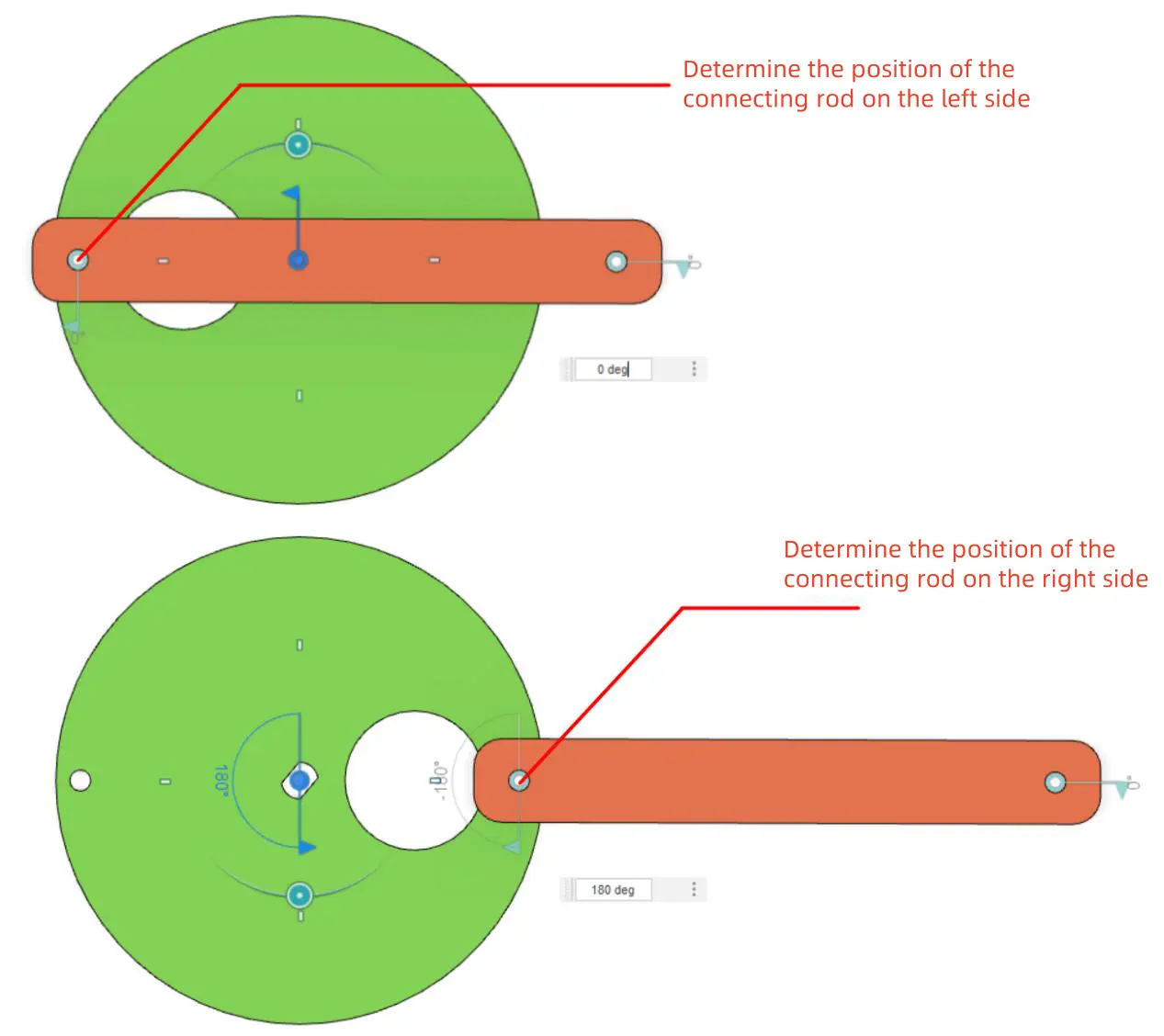
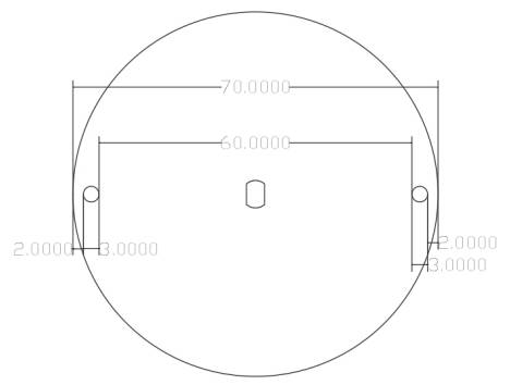
The disc of the crank-slider mechanism is connected to the connecting rod using an R3080 nylon rivet. Therefore, we need to drill holes on the edge of the disc for connecting the connecting rod, with a hole diameter of 3mm. From the previous analysis, we know that the diameter of the circular motion of this hole, along with the disc, must be greater than 40mm. Therefore, we can draw two holes on the disc, one on the left and one on the right, to facilitate determining the positions where the connecting rod moves to the leftmost and rightmost extremes.
To prevent the holes from being too close to the disc edge, we can reserve a 2mm allowance. This allows us to determine the spacing between the two holes (distance between inner walls) as 70 – (2 + 3) * 2 = 60mm.
Science Fact:
What’s the difference between hole spacing and hole pitch?
Hole spacing refers to the distance between the solid portions of two holes, specifically the distance between the hole walls. Hole pitch, on the other hand, refers to the center-to-center distance between two holes, that is, the distance from the center of the first hole to the center of the second hole.
Using the “Ellipse Tool” in the “Drawing Toolbox,” draw a circle with a diameter of 3mm on the canvas. Click “Rectangular Array” in the tool menu bar, and set the parameters in the pop-up window as follows: Horizontal Count 2, Horizontal Spacing 60mm, Row Offset 0mm, Vertical Count 1, Vertical Spacing 1mm, Column Offset 0mm. Click “OK” to obtain two circles. Right-click and select the grouping function to combine the two circles. Then, use the “Align” tool in the “Drawing Toolbox” to horizontally and vertically center-align them with the 70mm diameter disc (hereinafter referred to as the disc). This completes the design of the disc (crank), as shown in the figure below.
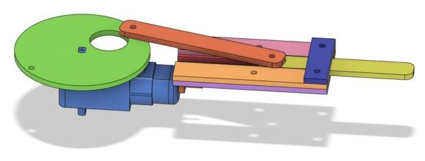
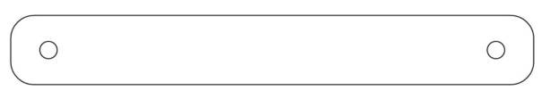
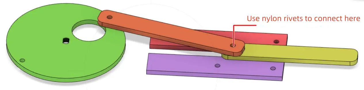
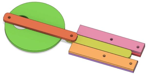
(4) Drawing the Connecting Rod
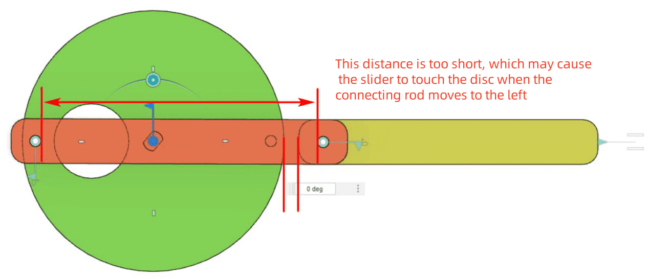
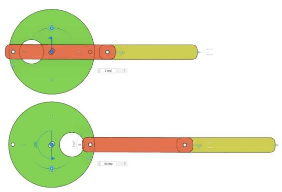
As seen in the diagram below, the connecting rod joins the disc and the slider (yellow represents the slider, red represents the connecting rod). To ensure that the slider does not collide with the disc during the operation of the crank-slider mechanism, the distance between the two holes on the connecting rod must be greater than the diameter of the disc. Therefore, we set the spacing between the two holes on the connecting rod to 74mm.
Using the “Ellipse Tool” in the “Drawing Toolbox,” draw a circle with a diameter of 3mm on the canvas. Click “Rectangular Array” in the tool menu bar and set the parameters as follows: Horizontal Count 2, Horizontal Spacing 74mm, Row Offset 0mm, Vertical Count 1, Vertical Spacing 1mm, Column Offset 0mm. Click “OK” to obtain two circles. Right-click and select the grouping function to combine the two circles.
Next, use the “Rectangle Tool” in the “Drawing Toolbox” to draw a rectangle with a width of 90mm and a height of 12mm on the canvas. Then, use the “Rounded Corner Tool” in the “Drawing Toolbox” to apply rounded corners to the rectangle’s four corners, setting the corner radius to 4mm, resulting in a rounded rectangle.
Click the “Selection Tool” in the “Drawing Toolbox” and select the rounded rectangle and the grouped two circles. Use the “Align” tool’s “Horizontal Center Alignment” and “Vertical Center Alignment” functions in the “Drawing Toolbox” to align both horizontally and vertically. Right-click and select the grouping function to combine the rounded rectangle and the two circles into a single entity, thus completing the design of the connecting rod.
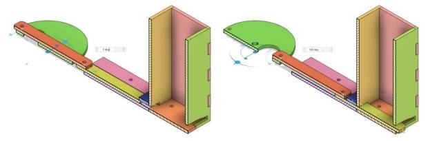
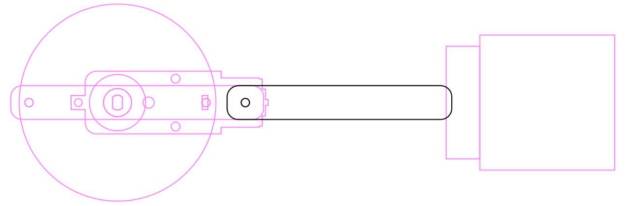
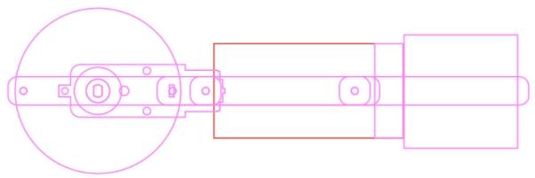
(5) Determining the Stroke of the Connecting Rod
Before determining the position of the slider, it is necessary to first determine the stroke of the connecting rod’s movement, which is the position of the connecting rod when it moves to the leftmost and rightmost points of the disc.
By clicking and selecting the connecting rod with the mouse, drag and align the left hole of the connecting rod with the leftmost hole on the disc. This determines the leftmost position of the connecting rod.
Using the same method, select the connecting rod and drag it to align the left hole of the connecting rod with the rightmost hole on the disc. This determines the rightmost position of the connecting rod, as illustrated in the following figure.
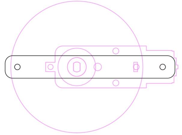
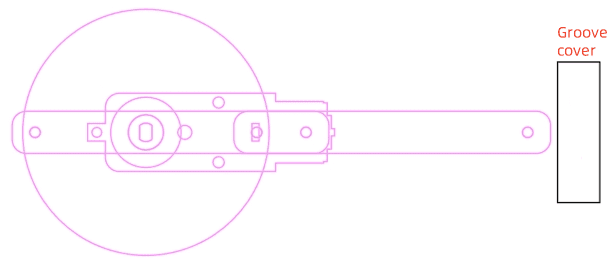
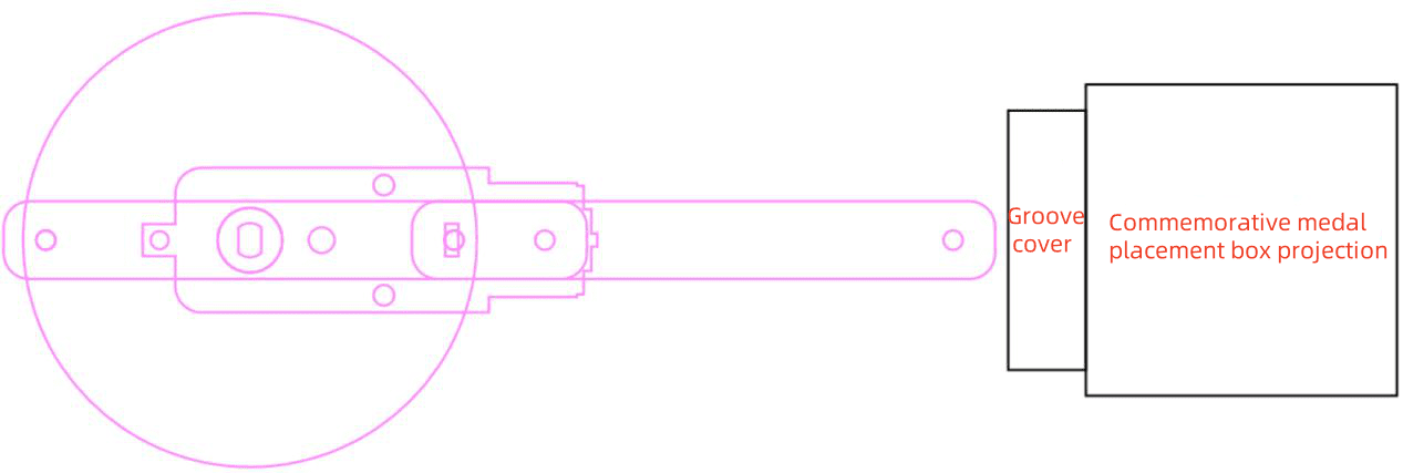
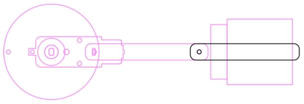
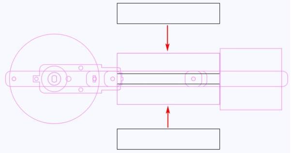
(6) Determining the Positions of the Recess Cover and Medal Holder
In the crank-slider mechanism, the recess restricts the slider’s movement trajectory. To prevent the slider from disengaging from the recess, we can add a baffle as a recess cover. Additionally, when the connecting rod moves to its rightmost position, it should maintain a certain clearance from the recess cover to ensure it does not collide with it.
(1) Adjusting the “TT Motor” Graphic
The crank-slider mechanism is powered by a TT motor, which drives the rotation of the disc (crank). Therefore, during the drawing process, the position of the disc can be determined based on the location of the TT motor shaft.
Select the “TT Motor” graphic from the “Open-Source Robot” option in the LaserMaker library and drag it onto the canvas.
The shaft of the TT motor connects to the disc. Observing the orientation of the TT motor in the image below, we can see that the shaft is located on the left side, while the “TT Motor” graphic in the library has the shaft on the right side. Therefore, we need to adjust the “TT Motor” graphic accordingly.
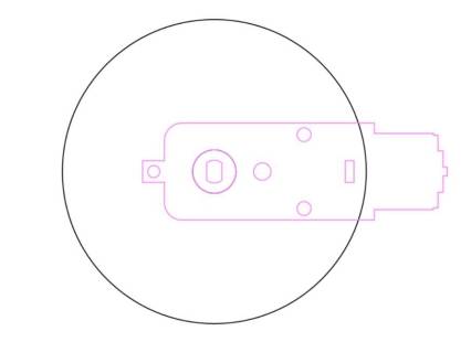
Using the ‘Rectangle Tool’ in the ‘Drawing Toolbox’, draw a square with a side length of 48mm on the canvas to represent the projection of the medal holder. Drag it to the right of the recess cover, next to it.
While holding the Ctrl key, select the rectangle representing the recess cover, the square representing the projection of the medal holder, and the disc. Use the ‘Align Tools’ in the ‘Drawing Toolbox’ and select the ‘Vertical Center Alignment’ function to vertically center-align all three components.
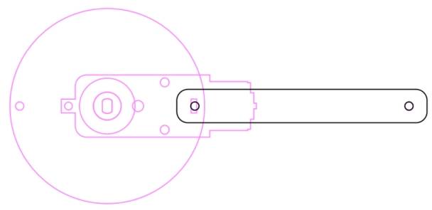
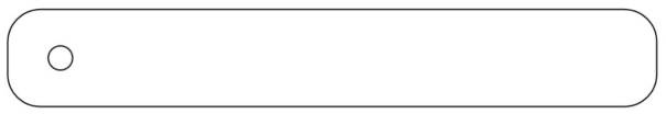
(7) Drawing the Slider
In our crank-slider mechanism, the slider performs a linear reciprocating motion to eject the commemorative medal while staying within the recess. To ensure this, when the slider moves to the leftmost position, its right end should remain under the recess cover, and when it moves to the rightmost position, its right end should extend outside the medal holder. This will be the basis for determining the length of the slider.
Now let’s design the slider, which is the yellow part in the figure. Using the ‘Rectangle Tool’ in the ‘Drawing Toolbox’, draw a rectangle with a width of 80mm and a height of 12mm on the canvas. Then, use the ‘Rounded Corner Tool’ in the ‘Drawing Toolbox’ to apply rounded corners to the four corners, setting the corner radius to 4mm, resulting in a rounded rectangle.
Using the ‘Ellipse Tool’ in the ‘Drawing Toolbox’, draw a circle with a diameter of 3mm on the canvas to represent the hole for connecting the slider to the connecting rod. Select the rounded rectangle and the circle, and use the ‘Align Tools’ in the ‘Drawing Toolbox’ to vertically center-align and left-align them. Then, select the circle and increase its x-coordinate by 5 to move it 5mm to the right. Finally, select both the rounded rectangle and the circle, right-click, and choose the grouping function to combine them, resulting in the completed drawing of the slider.
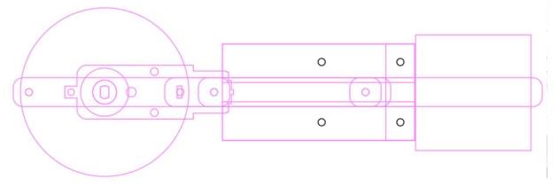
Select the slider drawing and drag it so that its hole aligns with the hole on the right side of the connecting rod when it is in the leftmost position. At this point, we notice that the rightmost end of the slider intersects with the position of the recess cover, indicating that when the slider moves to the leftmost position, its right end remains underneath the recess cover and will not disengage from the recess.
Using the same approach, select the slider drawing and drag it so that its hole aligns with the hole on the right side of the connecting rod when it is in the rightmost position. We will find that the right end of the slider has extended outside the medal holder, indicating that when the slider moves to the rightmost position, it can push the commemorative medal out. Therefore, the design of the slider drawing is reasonable.
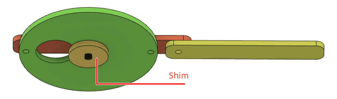
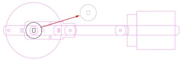
(8) Drawing the Gasket for the Disc
Since the TT motor is fixed with M3*30 flat-head screws, the protruding screw heads may hinder the rotation of the disc. Therefore, we can add a gasket under the disc to solve this problem. This also resolves the issue of the R3080 nylon rivet scratching the base plane.
Use the “Ellipse Tool” in the “Drawing Box” to draw a circle with a diameter of 20mm on the canvas. Use the “Align Center Horizontally” and “Align Center Vertically” functions in the “Alignment Tool” to align the circle horizontally and vertically with the disk. Now, the circle with a diameter of 20mm is horizontally and vertically aligned with the TT hole position. We can now copy the circle with a diameter of 20mm and the TT hole position to use as a gasket. As shown in the figure below, the black part is the gasket.
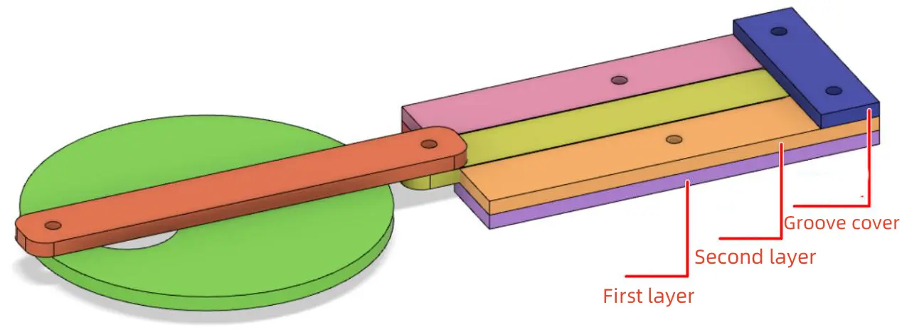
(9) Drawing the groove
The groove can be used to limit the movement trajectory of the slider. The thickness of the groove plus the groove cover is equivalent to 3 layers of basswood board, which is 9mm.
Using the “Rectangle Tool” in the “Drawing Box,” draw a rectangle with a width of 80mm and a height of 40mm on the canvas. Set the layer to red and drag it to align with the right side and vertically center with the groove cover. This can serve as a reference position for the groove, as shown in the red shape in the figure below.
Since the nylon rivets are used to connect the disk, connecting rod, and slider, and the head of the nylon rivet has a certain thickness, the first layer of the groove needs to be hollow to provide space for the linear movement of the nylon rivet connecting the slider and connecting rod.
Select the groove cover rectangle and drag it to an empty space on the canvas for easier drawing. Use the “Rectangle Tool” in the “Drawing Box” to draw a rectangle with a width of 80mm and a height of 16mm on the canvas. Duplicate it using the copy-paste method to create the first layer of the groove. Select one of the rectangles and the red rectangle above, and use the “Align Center Horizontally” and “Align Top” functions in the “Alignment Tool” to align the rectangle horizontally and vertically with the red rectangle. Repeat the same steps to align the other rectangle horizontally and vertically with the red rectangle. As shown in the figure below, the two black rectangles represent the first layer of the groove.
Next, we need to draw the second layer of the groove, which primarily serves as a limiter to restrict the slider’s movement to a straight reciprocating path.
Using the “Rectangle Tool” in the “Drawing Box,” draw a rectangle with a width of 80mm and a height of 14mm on the canvas, and duplicate it to create the second layer of the groove. Select one of the rectangles and the red rectangle above, and use the “Align Center Horizontally” and “Align Top” functions in the “Alignment Tool” to align the rectangle horizontally and vertically with the red rectangle. Repeat the same steps to align the other rectangle horizontally and vertically with the red rectangle. As shown in the figure below, the two black rectangles represent the second layer of the groove.
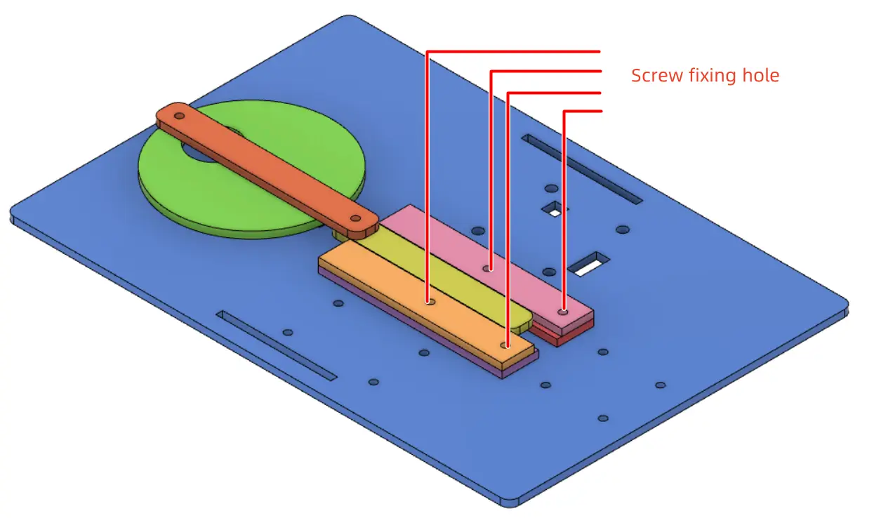
To secure the groove and groove cover to the base plate, we can pre-drill screw holes in the groove, groove cover, and base plate for fixing.
Select the groove cover rectangle and drag it back to its original position. Use the “Ellipse Tool” in the “Drawing Box” to draw a circle with a diameter of 3mm on the canvas. Duplicate this circle three times and drag them to suitable positions on the groove cover and groove as screw holes. Note that the screw holes should be positioned as far to the right as possible to prevent the connecting rod from being obstructed by the screws during movement.
3.Drawing the Medal Display Case
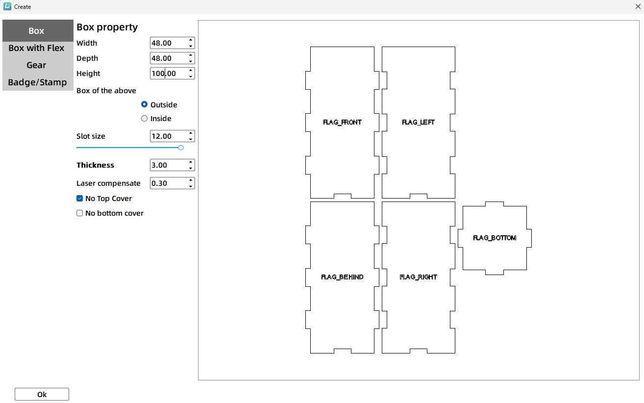
(1) Drawing a Rectangular Box
Based on the previous steps, we have determined the bottom projection of the medal display case to be a square with a side length of 48mm. From this, we can determine the dimensions of the medal display case.
Using the “Creation” tool in the “Toolbar,” select the “Rectangular Box” function and modify the parameters:
Box Properties: Box Length 48mm, Box Width 48mm, Box Height 100mm (these are the external dimensions of the box); Groove Size 12mm (if applicable), Material Thickness 3mm, Laser Compensation 0.1mm. To facilitate placing the medal inside, you can set the box to have no top cover.
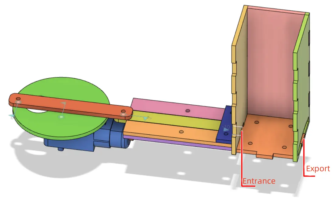
(2) Drawing the Slider Entry and Medal Exit
The principle of dispensing medals in this project is as follows: the medals are stacked in the medal display case, and the slider enters through the entry of the case, pushing the medals out through the exit. Then, the slider retracts, and the next medal falls from the box, repeating this process.
To allow the slider to move smoothly, the entry should be slightly larger than the slider. Similarly, the exit should be slightly larger than the medal. However, due to gravity, medals can easily get stuck during the ejection process. Therefore, the exit should be designed with an arc-shaped section to facilitate the medals falling out.
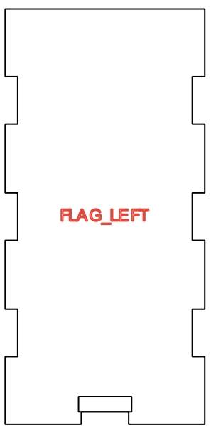
To draw the slider entry, use the “Rectangle Tool” in the “Drawing Box” to draw a rectangle with a width of 13mm and a height of 3.2mm on the canvas. Drag and position it so that it aligns with the edge of the mortise on the inside left side of the box, ensuring it is horizontally centered.
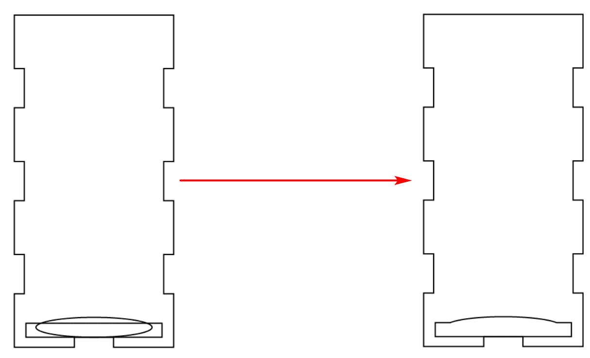
To draw the medal exit, use the “Rectangle Tool” in the “Drawing Box” to draw a rectangle with a width of 41mm and a height of 4.2mm on the canvas. Next, use the “Ellipse Tool” to draw an ellipse with a width of 30mm and a height of 5mm. Select the rectangle and the ellipse, and use the “Align Center Horizontally” and “Align Bottom” functions in the “Alignment Tool” to align them horizontally and vertically. Then, use the “Union” tool in the “Drawing Box” to merge the rectangle and ellipse into a single shape. Finally, drag and position this shape so that it aligns with the edge of the mortise on the inside right side of the box, ensuring it is horizontally centered.
(3) Drawing the Fixation Holes for the Medal Display Case
After determining the position of the medal display case in previous steps, we will now draw the fixation holes for the case. The medal display case consists of a bottom surface and four sidewalls (the bottom and sidewalls can be represented by an exploded view for clarity). We will design the fixation holes on the bottom surface to secure the medal display case to the base plate using screws and nuts.
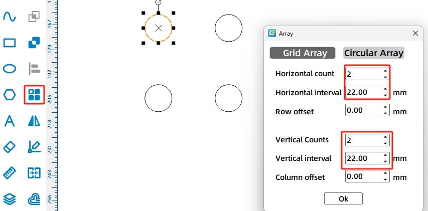
Using the “Ellipse Tool” in the “Drawing Box,” draw a circle with a diameter of 3mm on the canvas. Click on “Array” in the “Drawing Box” and select “Rectangular Array.” In the pop-up window, set the following parameters: Horizontal Count 2, Horizontal Spacing 22mm, Row Offset 0mm, Vertical Count 2, Vertical Spacing 22mm, Column Offset 0mm. Click “OK” to obtain four circles. Select the four circles, right-click, and choose the “Group” function to combine the four circles into a single object, representing the fixation holes for securing the medal display case to the base plate.
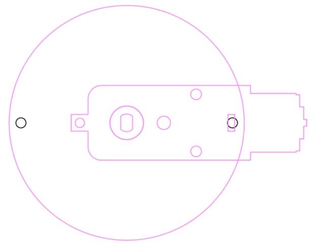
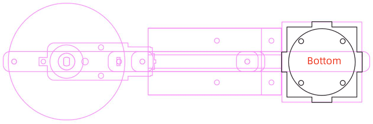
Use the “Ellipse Tool” in the “Drawing Box” to draw a circle with a diameter of 40mm on the canvas, representing the reference position for the medals. Select the “bottom surface” of the box, the 40mm diameter circle, the four fixation holes, and the projection of the medal display case. Use the “Align Center Horizontally” and “Align Center Vertically” functions in the “Alignment Tool” to align all four components both horizontally and vertically. As seen in Figure 8-50, when the medals are placed in the box, they will overlap the screws securing the box, ensuring no interference with the ejection of the medals. Select the “bottom” panel of the box and the four fixation holes, right-click, and choose the “Group” function to combine them into a single object, representing the bottom surface of the medal display case with the fixation holes.
Drawing the Base
After designing the crank slider mechanism and medal display case, we’ll proceed to design the base.
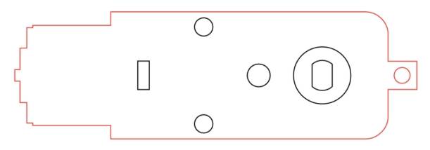
(1) Drawing the Base Plate
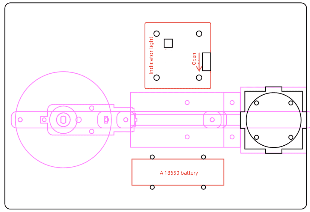
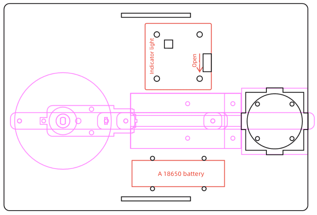
The base plate will secure the crank slider, medal display, OSROBOT receiver, 18650 batteries, and TT motors.
Select “OSBOBOT2 Control Board (Sinked)” from the Open Source Robotics section in LaserMaker and rotate it 270° three times using the rotation tool. Place it above the groove.
Choose “18650 Battery Strap Fixation” from the same section, remove excess parts, and place it below the groove.
Measure the dimensions of the components and determine the base plate size as 220mm wide x 150mm high.
Draw a 220mm x 150mm rectangle with rounded corners (radius of 4mm) using the Rectangle and Corner Rounding tools. Place the components in suitable positions within the rectangle to complete the base plate draft.
(2) Drawing the Mortise of the Base Plate
As the TT motor, OSROBOT receiver board, and 18650 batteries are fixed underneath the base plate, a double-bracket structure is adopted for the medal dispenser’s base.
Next, we will draw the mortise of the base plate. Using the ‘Rectangle Tool’ in the ‘Drawing Box’, draw a rectangle with a width of 50mm and a height of 3mm. Click on ‘Rectangular Array’ in the ‘Toolbar’, and set the parameters as follows: Horizontal Count 1, Horizontal Spacing 0mm, Row Offset 0mm, Vertical Count 2, Vertical Spacing 130mm, Column Offset 0mm. Click ‘OK’ to obtain two rectangles. Right-click and use the grouping function to combine them. Then, use the ‘Align’ tool to horizontally and vertically center the two rectangles with the base plate. This completes the design of the mortise for the base plate.
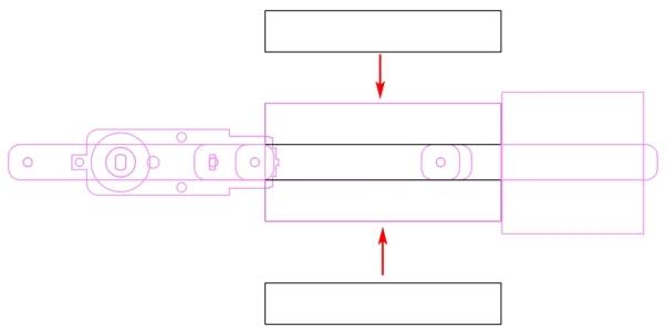
(3) Drawing the Brackets
The brackets provide support for the base plate and prevent the TT motor, OSROBOT receiver board, and 18650 batteries from touching the ground.
Use the ‘Rectangle Tool’ in the ‘Drawing Box’ to draw a rectangle with a width of 220mm and a height of 30mm. Add tenons to the rectangle to fit the mortise on the base plate. To ensure a secure mortise-and-tenon joint, design a rectangular tenon with a width of 50.5mm and a height of 3mm, where the extra 0.5mm is for laser compensation. Align the bottom of the tenon with the top of the 220mm x 30mm rectangle and horizontally center them. Select both rectangles and use the ‘Union’ tool in the ‘Drawing Box’ to merge them into a single bracket. Duplicate this bracket to obtain the second one, thus completing the design of the base’s bracket pair.
With this, we have completed the drawing design of the medal dispenser.
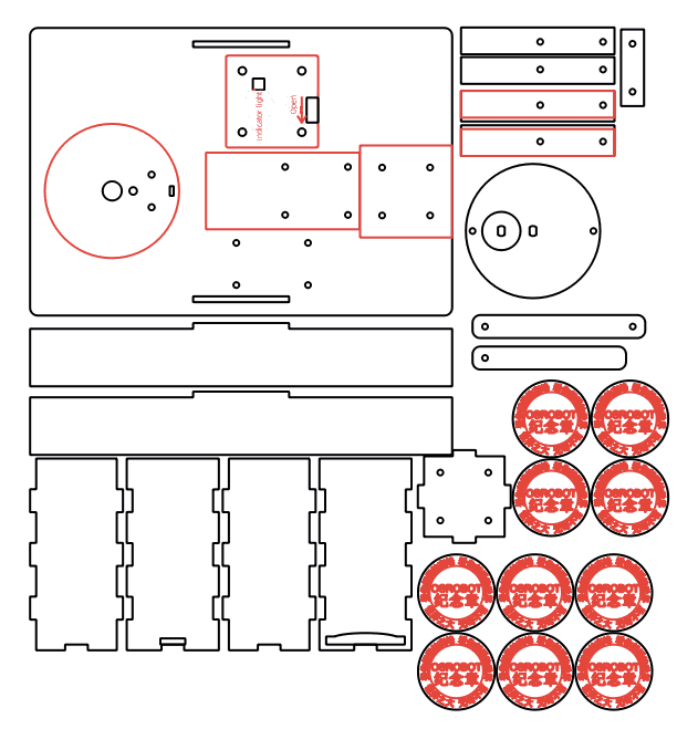
Layout
So far, the draft design is basically complete.
Select all elements of the sketch, right-click, and choose “Ungroup” to break apart all groups. Select and copy each part of the medal dispenser from the sketch, set the layers, and arrange them to obtain the final production drawing.
Laser Cutting
After completing the drawing design, we can set the cutting parameters and proceed with the cutting process.
Setting Parameters
(1) Outlining
Double-click the red block in the processing area, select “Basswood Plywood” as the material, choose “Outlining” as the processing method, and set the cutting depth to 0.10mm. Click “OK” to confirm.
(2) Cutting
Double-click the black block in the processing area, select “Basswood Plywood” as the material, choose “Cutting” as the processing method, and set the cutting depth to 3.00mm. Click “OK” to confirm.
Starting the Fabrication
Turn on the laser cutting machine and the laser switch. Once the “Start Fabrication” button turns blue, click it. Once the drawing is uploaded to the laser cutting machine, press the “Start” button on the machine’s panel to begin cutting.
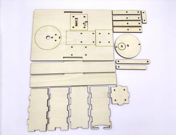
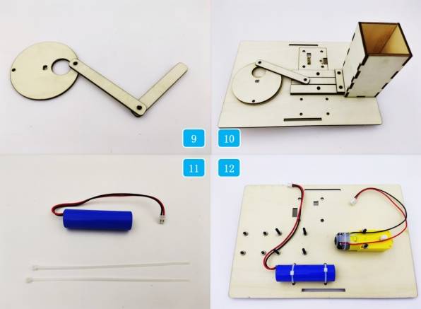
Model Assembly
After processing in the fabrication workshop with the laser cutting machine, the cut parts will look like the following:
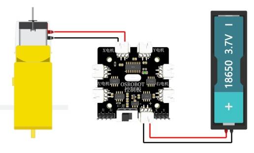
Circuit Wiring
To activate the medal dispenser, wiring is essential. Staff at the amusement park can follow the wiring diagram below during the assembly process.
Structural Assembly
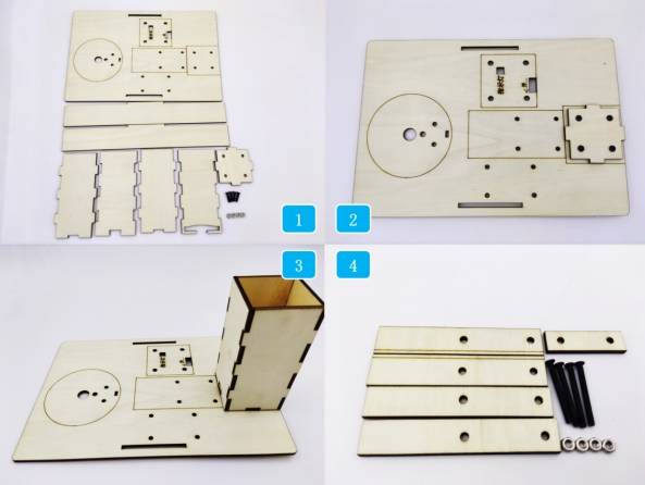
After obtaining the laser-cut parts, we can assemble the model according to the following steps:
Step 1: Locate the base plate and the relevant parts for the medal holder box.
Step 2: Secure the bottom of the medal holder box to the base plate using screws and nuts.
Step 3: Assemble the front, back, left, and right sides of the medal holder box in sequence.
Step 4: Locate the relevant components for the grooves.
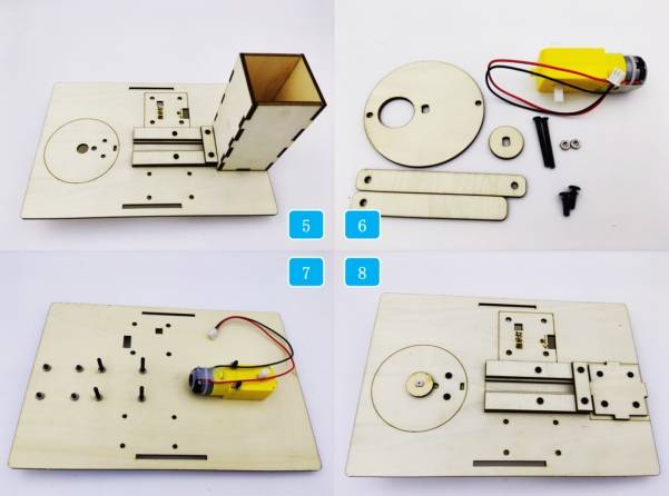
Step 5: Secure the groove-related parts to the base plate using screws and nuts.
Step 6: Locate the TT motor and crank-slider mechanism components.
Step 7: Fix the TT motor to the base plate with screws and nuts.
Step 8: Install the spacer onto the shaft of the TT motor.
Step 9: Assemble the connecting rod and slider to the disc using R3080 nylon rivets.
Step 10: Install the crank-slider mechanism onto the TT motor and groove.
Step 11: Locate the battery and cable ties.
Step 12: Secure the battery to the base plate using cable ties.
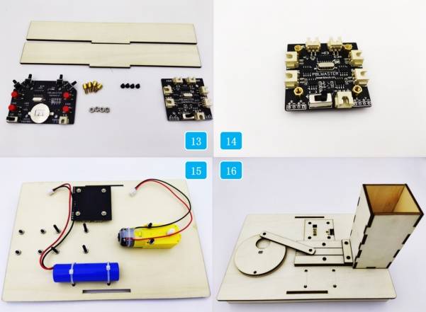
Step 13: Locate the base bracket, OSROBOT2 control board, screws, nuts, and copper standoffs.
Step 14: Secure the copper standoffs to the OSROBOT2 control board.
Step 15: Fix the OSROBOT2 control board to the base plate.
Step 16: Install the base bracket.
After assembly, amusement park staff can turn on the control panel, switch the remote to the battery mode, pair it, and operate it to dispense medals.
summary,
In summary, the medal dispenser is now complete. Through this process, we learned how to design and fabricate a crank-slider mechanism, enabling automatic medal dispensing. Next, the M Planet amusement park manager will inspect it. We believe the exquisite medals and the magical experience of automated dispensing will create wonderful memories for visitors.
Reflections and Enhancements
While the medal dispenser designed and built for this project has generally achieved the function of remotely dispensing medals, there are a few areas for improvement. Firstly, during the dispensing of the last medal, it tends to get stuck. How can we resolve this issue, designers? Secondly, the current design lacks aesthetic appeal. Could we further enhance its appearance?
In our daily lives, many machines utilize the crank-slider mechanism. Do you know of any other applications where this mechanism is used? Additionally, we encourage designers to harness their imagination and utilize the crank-slider mechanism to create more innovative projects.


.png "laser cutter Globle")


