Origin of the Project

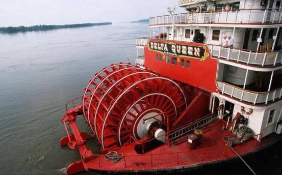
Up until now, the various design work in the Creation Factory has been proceeding smoothly. The designers are now busy designing a novel, interesting, and distinctive water activity device. The design of this water activity device is inspired by the paddlewheel boat.
A paddlewheel boat is a type of vessel that differs from conventional propeller-driven boats. It has two paddlewheel devices with numerous paddle blades placed on both sides of the hull. When the motor rotates, it drives the paddle blades on the paddlewheel devices to move as well. The paddle blades stir the water, and the boat moves. It is sure to satisfy the curiosity of players on Planet M and bring them more joy.
Before the design begins, let’s first take a look at how paddlewheel boats appear in real life, and then work with the designers to use laser cutting software to design an interesting water cruise device.
Determining the Design Scheme
Analysis of the Work
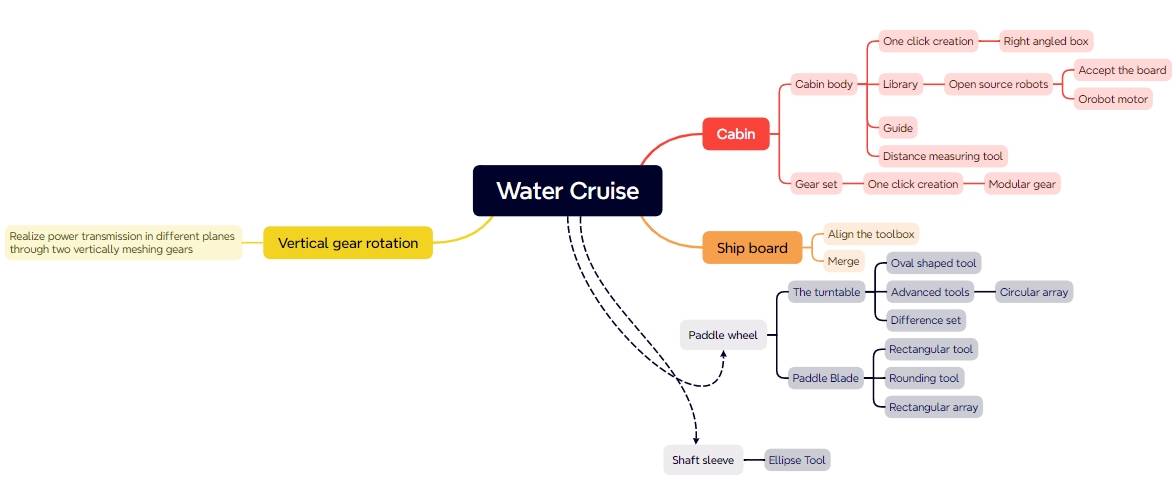
First, we can observe that the paddlewheel boat moves because the motor drives the rotation of the paddlewheel, and the paddle blades on the paddlewheel stir the water, causing the boat to move in the opposite direction of the rotation. In previous designs, objects connected to the motor shaft, such as the lucky spin wheel or small car wheels, had their rotating parts directly connected to the motor shaft. Theoretically, we could use a similar approach and have the motor directly drive the paddle blades to rotate. However, since this work is meant to operate on water, for waterproofing purposes, it is necessary to keep the motor as far from the water surface as possible. In this case, we can design a vertical transmission gear set to achieve this.
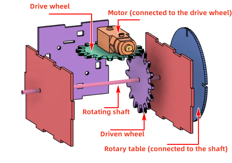
Please refer to the attached figure for reference.
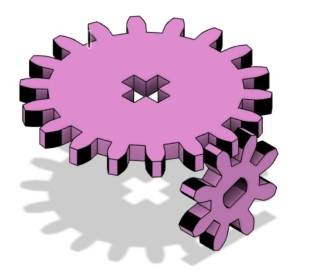
The vertical gear is fixedly connected to the motor shaft, while the horizontal gear is connected to the paddlewheel boat’s paddlewheel. When the motor operates, it drives the vertical gear to rotate. Since the gears are meshed with each other, the horizontal gear will also move, causing the paddle blades on the paddlewheels on both sides to rotate.
Additionally, to increase the buoyancy of the water cruise, we can consider adding a layer of material with stronger buoyancy underneath the hull, such as a layer of KT board or foam board, to allow the boat to float on the water for a longer time.
Materials List
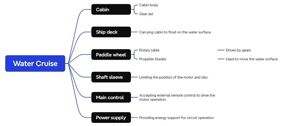
With the basic design scheme for the water cruise determined, we can proceed to create the project using the various components provided by the Creation Factory. We will continue to utilize the remote controller and receiver, the treasures of the Creation Factory, to enable remote control of the water cruise.
Materials List:
Number
Name
Quantity
1
2.4G Remote Control
1
2
2.4G Receiver
1
3
TT Motor
1
4
18650 Battery
2
5
18650 Battery Holder
1
6
Basswood Board (40cm60cm3mm)
1
7
M3/M4 Screws, Nuts, and Nylon Standoffs
Several
8
KT Board (40cm60cm3mm)
1
9
Bamboo Stick (Diameter 4mm, Length Approx. 200mm)
1
Number | Name | Quantity |
1 | 2.4G Remote Control | 1 |
2 | 2.4G Receiver | 1 |
3 | TT Motor | 1 |
4 | 18650 Battery | 2 |
5 | 18650 Battery Holder | 1 |
6 | Basswood Board (40cm60cm3mm) | 1 |
7 | M3/M4 Screws, Nuts, and Nylon Standoffs | Several |
8 | KT Board (40cm60cm3mm) | 1 |
9 | Bamboo Stick (Diameter 4mm, Length Approx. 200mm) | 1 |
Structural Design
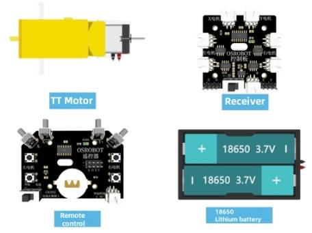
With all the components ready, we move on to the design phase. The entire project can be divided into four parts: the cabin, the hull, the paddlewheel, and the shaft sleeve. We’ll establish the parts list following the principle of inside-out.
Parts List
The structural parts for this project design consist of 4 components, as shown in the following Table.
Part No.
Part Name
Quantity
Function
1
Cabin
1
Houses the gear assembly, motor, and receiver board
2
Hull
1
Supports the cabin and floats on the water
3
Paddlewheel
1
Driven by the gear assembly, propels the boat forward through paddle rotation
4
Shaft Sleeve
10
Gear shaft sleeves and paddlewheel limiter shaft sleeves
Part No. | Part Name | Quantity | Function |
1 | Cabin | 1 | Houses the gear assembly, motor, and receiver board |
2 | Hull | 1 | Supports the cabin and floats on the water |
3 | Paddlewheel | 1 | Driven by the gear assembly, propels the boat forward through paddle rotation |
4 | Shaft Sleeve | 10 | Gear shaft sleeves and paddlewheel limiter shaft sleeves |
After determining the parts list, we can proceed with laser modeling.
Laser Modeling
- Drawing the Cabin
The cabin consists of a body and a gear assembly. To avoid any mismatch between the gear assembly and the cabin dimensions, we can first design the gear assembly and then create the outer shell of the cabin, adjusting its size based on the gear assembly’s size and placement.
- Drawing the Gear Assembly
Gears can be simply understood as wheels with teeth on their edges. A gear assembly is a device that consists of two or more gears that transmit motion through their teeth. When we open the case of a TT motor, we find a gear assembly inside. A gear mounted on the motor shaft is known as the driver gear. There is another gear vertically aligned and meshed with the driver gear, called the driven gear. As the driver gear rotates, it drives the motion of the driven gear.
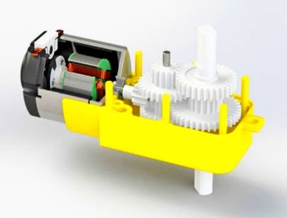
In designing the paddlewheel boat, two gears can be designed. One acts as the driver gear mounted on the motor shaft, and the other acts as the driven gear mounted on the paddlewheel’s transmission shaft. The driver and driven gears are meshed vertically, allowing the rotation of the motor in the horizontal direction to drive the vertical gear, thereby propelling the paddlewheel boat.
Once the design concept is clear, we can proceed with the construction of the gear assembly.
(1) Using the gear tool provided in the LaserMaker software, select “Creation” from the toolbar at the top of the software. From the pop-up menu, choose “Modular Gear,” and set the gear properties with a module of 4, a shaft diameter of 4mm, and a tooth count of 16.
The module is a basic parameter for modular gears and determines the size of the gear. Gears with the same number of teeth but a larger module value will have a larger diameter. You can adjust this value based on the dimensions of your project. By adjusting the tooth count and module, you can generate gears of the appropriate size. The shaft diameter parameter refers to the diameter of the shaft passing through the center of the gear. Since we are using a 4mm wooden rod as the shaft, setting the diameter parameter to 4mm allows for easy insertion and connection of the rod or motor shaft through the gear.
After confirming the settings, two gears of the same size will be generated.
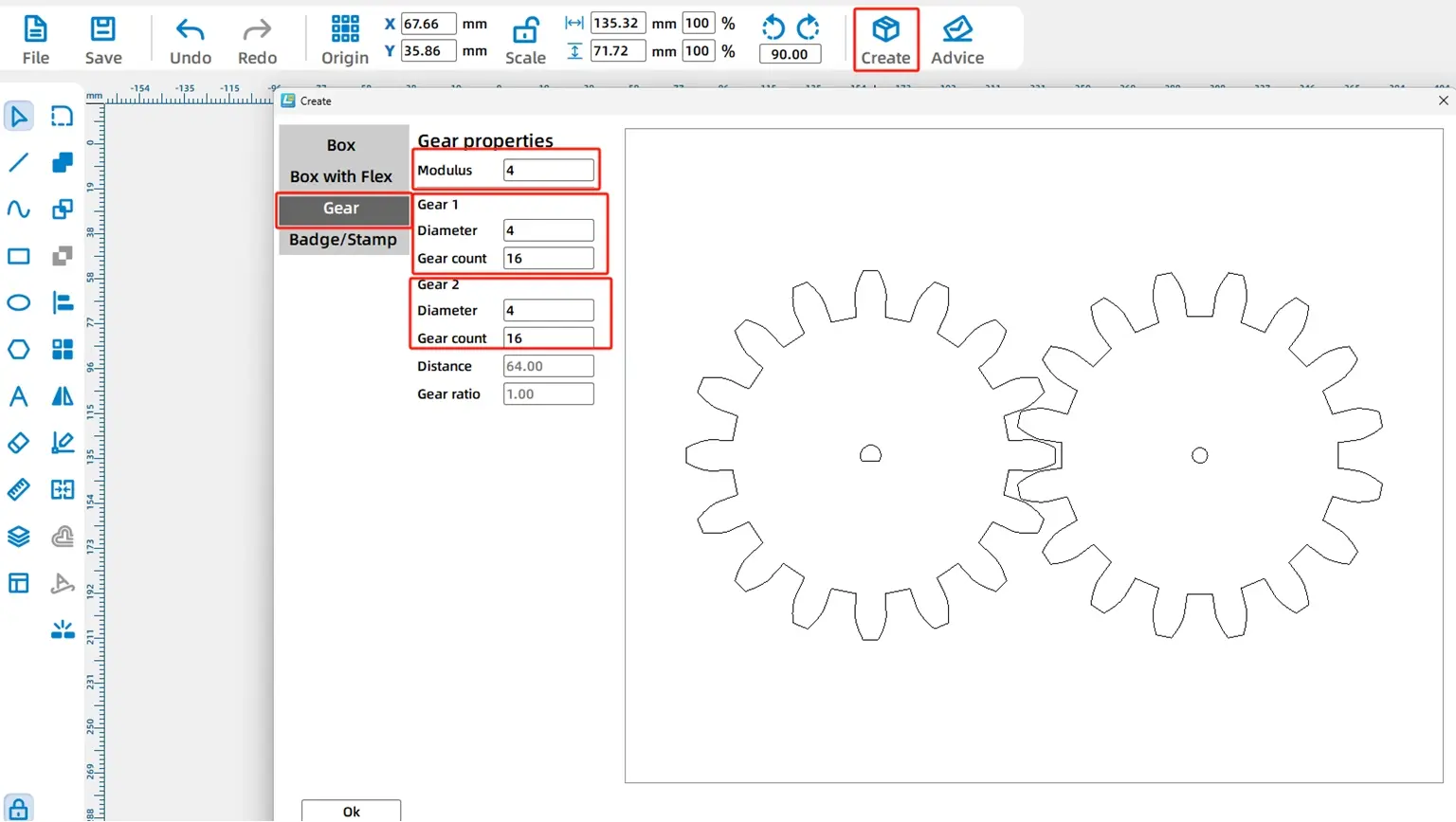
Since we will use one of the generated gears to connect with the TT motor and the other with a 4mm wooden rod, we need to modify the design of the gears created with the ‘Modular Gear’ tool.
(2) Select and delete the N20 shaft hole in the center of the left gear. Then, from the “Mechanical Parts” section in the right-side library, choose the “TT Hole” option.
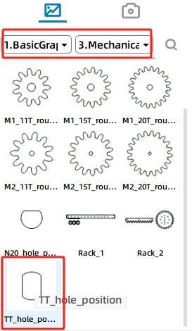
Drag and place the TT motor hole onto the gear graphic, adjusting its position until the snap lines indicate that the hole is centered within the gear. As shown in the figure below.
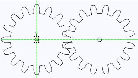
Once the TT motor hole is in place, you can temporarily set aside the completed gear graphic in a corner of the drawing area and proceed to design the rest of the cabin.
Drawing the Cabin
The main purpose of the cabin for this watercraft is to house the transmission mechanism and the circuit board. This can be achieved by designing a cubic box.
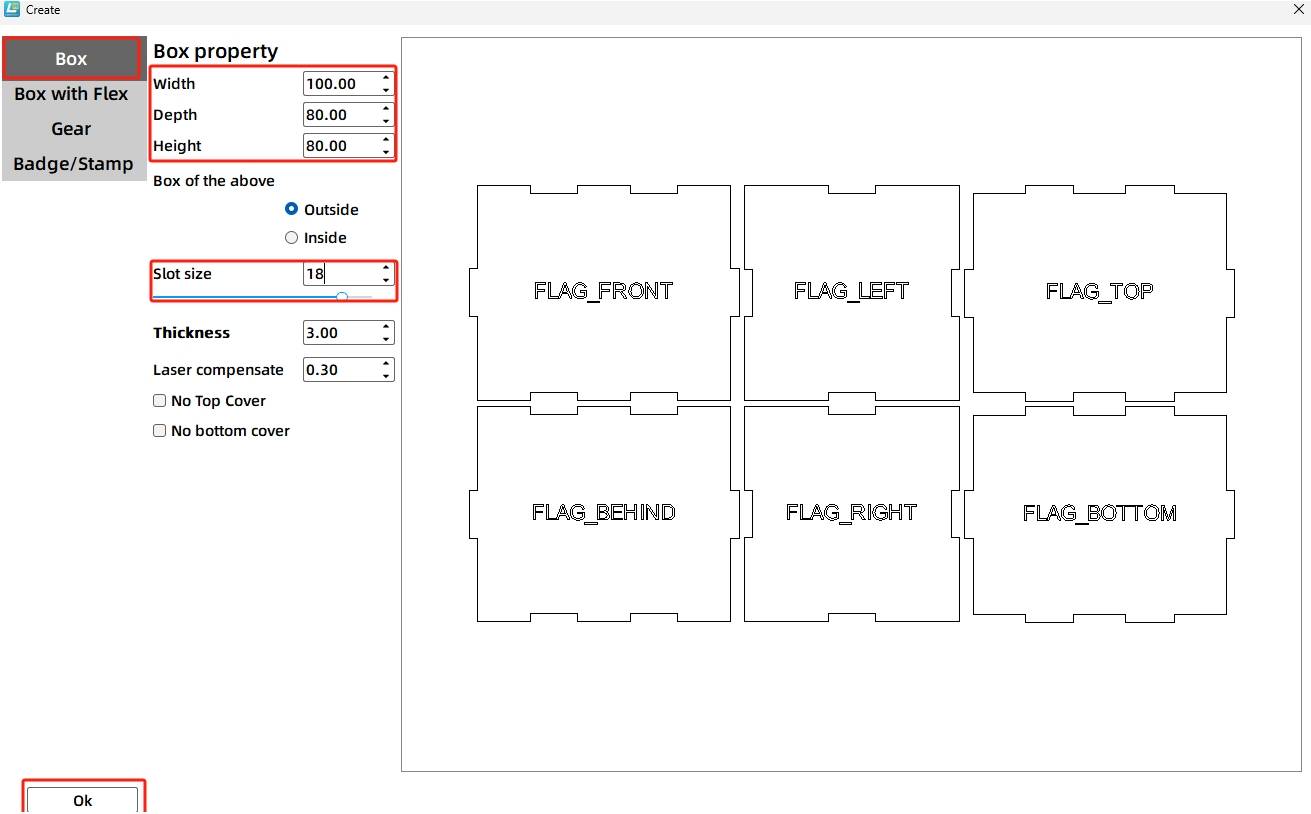
(1) In the toolbar, select “Creation” and from the pop-up menu, choose “Rectangular Box.” Set the length, width, and height of the box to 100mm, 80mm, and 80mm, respectively. Adjust the groove size to 20mm. The parameters are shown in the figure below. Click “Confirm” after making the modifications.
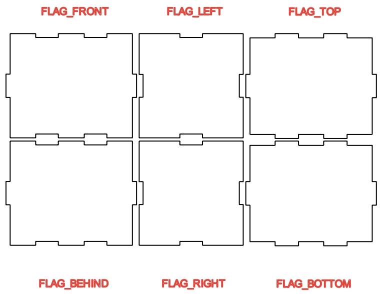
(2) Drag and position the generated prompt text on the six faces using the mouse, as shown in the following figure.
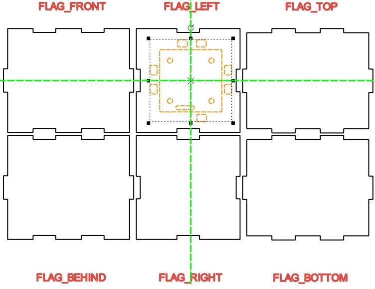
(3) In the library on the right, find the “Open-Source Robotics Hardware” section and select “2.0 Control Board (External)”. Place it in the center of the “left” panel. When green crosshairs appear, it indicates the graphic is centered. The completed layout is shown below:
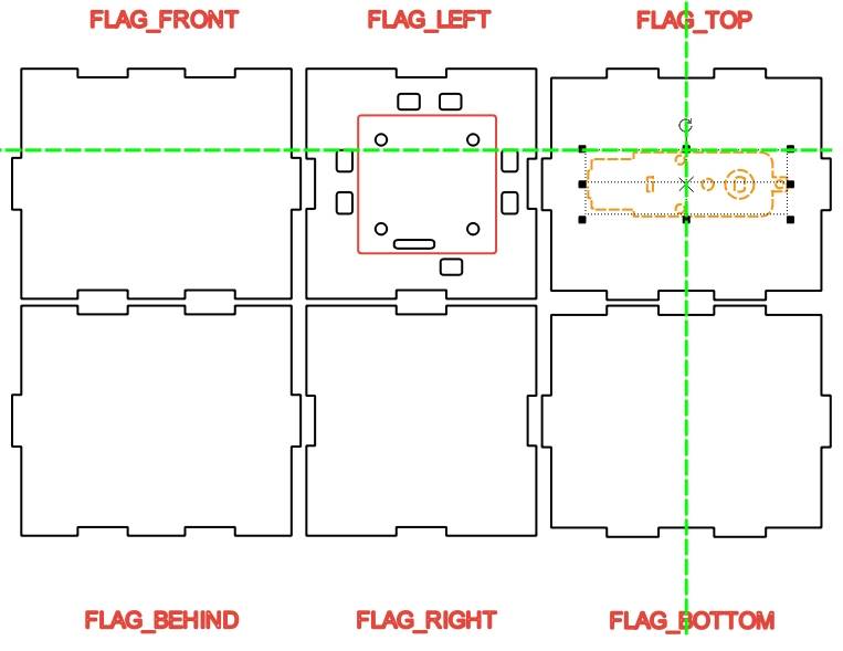
(4) From the library on the right, navigate to the “Open-Source Robotics Hardware” section, select “TT Motor,” and position it in the center of the top panel of the unfolded view of the cabin.
(5) A 3D sketch illustrates the positional relationship of the gear assembly. The motor is securely connected to the driver gear via the shaft hole. The shaft passes through the “front” panel hole, the driven gear hole, and the “rear” panel hole. To ensure vertical engagement between the gears, the centers of the three holes must align on the same line.
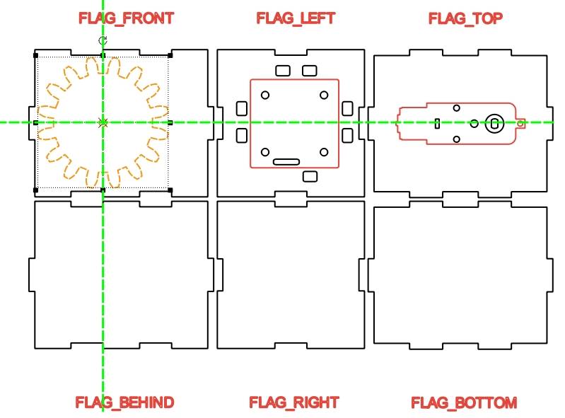
First, ensure that the shaft holes on the front and rear panels are aligned. Move the circular gear set created in the previous step and place it on the front panel, positioning the gears as close to the edge as possible.
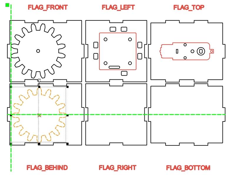
Using the same method, place the other gear on the rear panel, ensuring alignment with the previous gear.
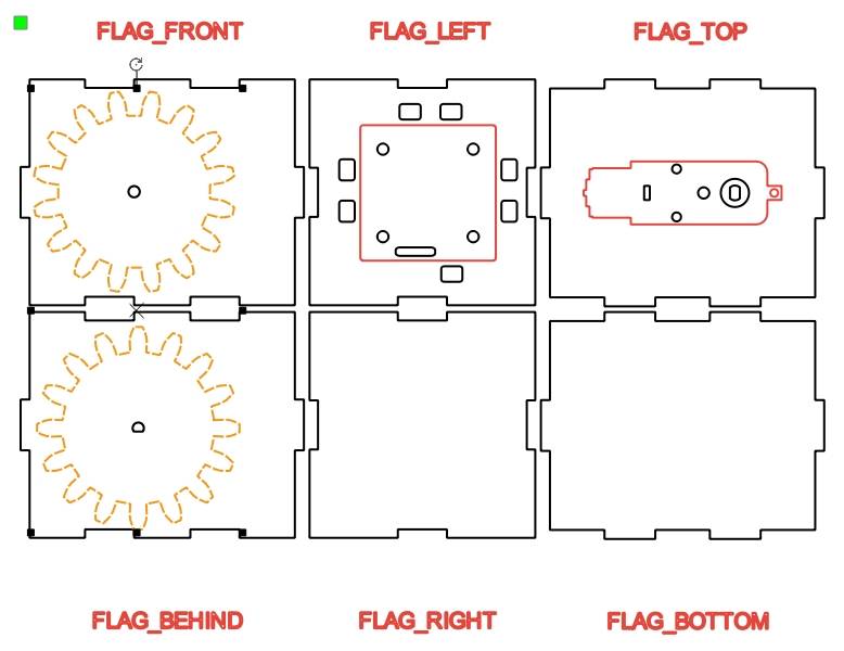
By adjusting the placement of the gears, we determine the position of the shaft hole. The outer contours of the gears serve as guides, differentiated by different colors for display.
(6) Next, adjust the position of the motor shaft hole. The motor is mounted on the “top” panel of the unfolded view. Move it to the bottom of the “rear” panel and align it with the “front” and “rear” panels. Add a vertical guideline to the left of the three graphics to check alignment. Adjust the position of the prompt text accordingly.
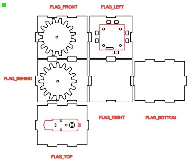
(7) As you can see, the current motor shaft hole is not aligned with the shaft holes on the front and rear panels. Therefore, you need to adjust the motor’s position. First, select all the TT motor graphics, and then use the horizontal flip function from the Toolbox to make the necessary adjustments.
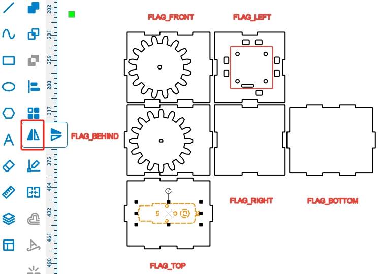
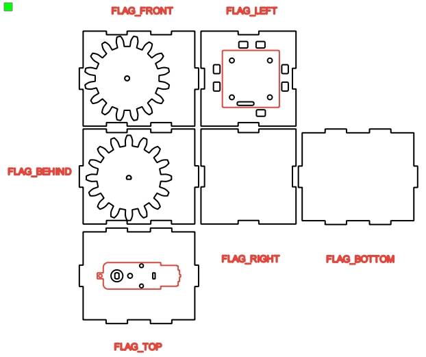
(8) To ensure that the gear shaft holes in the two boards are aligned on the same axis, you can use guidelines for positioning. Press and hold the left mouse button on the ruler on the left side of the canvas and drag it to the right to create a vertical guideline. Draw two guidelines based on the left edge of the graphics and the two shaft holes, ensuring that the guidelines pass through the centers of the two shaft holes.
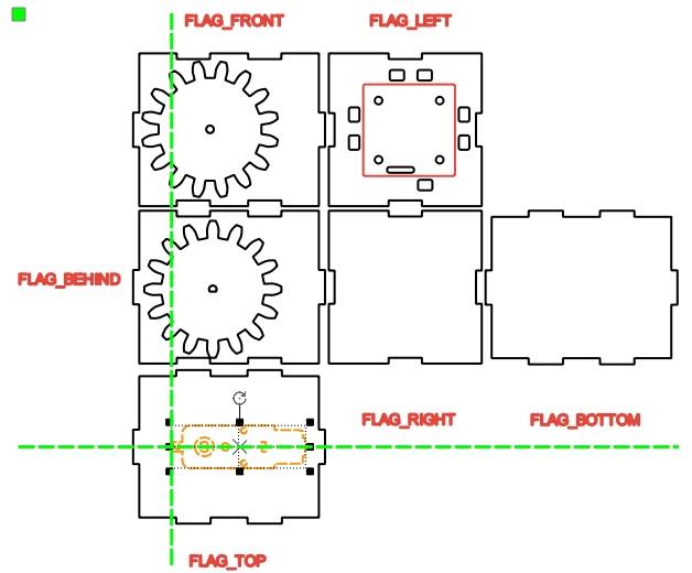
(9) Continue using the guidelines to adjust the shaft hole of the TT motor, ensuring that the gear centers and the TT motor shaft hole are on the same axis. Select the TT motor drawing using the “Select” tool, right-click and choose “Group.” Drag the TT motor graphic with the mouse to align the center of its shaft hole with the centers of the two gears above.
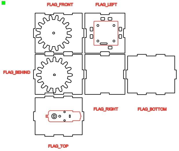
(10) Finally, delete the outlines of the two gears and keep only the shaft holes.
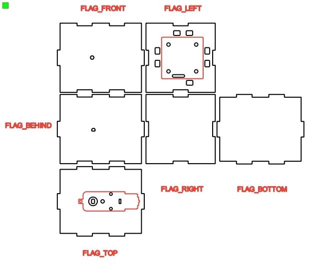
Select the TT motor, ungroup it, and delete the motor’s outline as well as the elliptical shape at the center of the motor shaft hole.
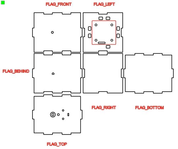
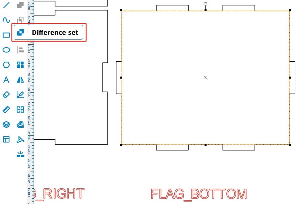
(11) The hull shell is installed on the deck, requiring mortise and tenon joints to facilitate installation. Modify the panel labeled “bottom” by removing the outline and retaining only the mortise interface. Consider drawing a rectangle on the “bottom” panel and using the “difference” function to create the tenon hole.
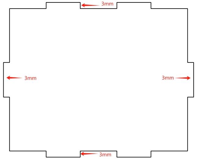
(12) Select the “bottom” panel. By observing the graphical dimensions in the menu bar, we can determine that its width is 106.4mm and height is 86.4mm.
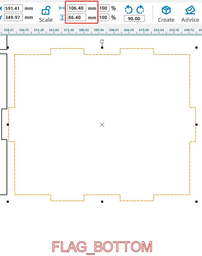
The panel has tenons on both the horizontal and vertical sides, and the length of each tenon is equal to the thickness of the wood, which is 3mm. In other words, subtracting 6mm from the length and width of the top panel gives you the internal dimensions of the graphic.
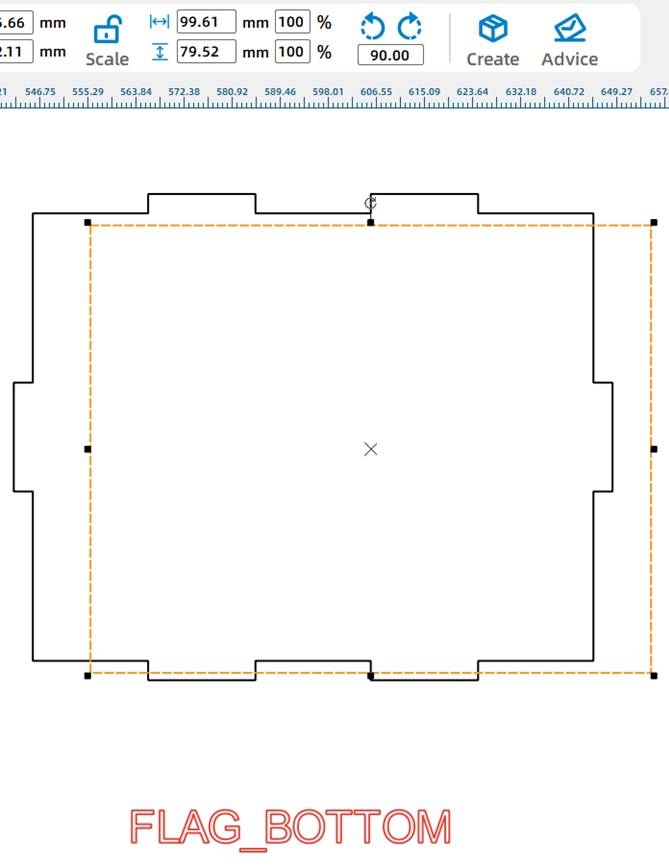
Next, select the “Rectangle” tool and draw a rectangle with a width of 99.61mm and a height of 79.52mm.
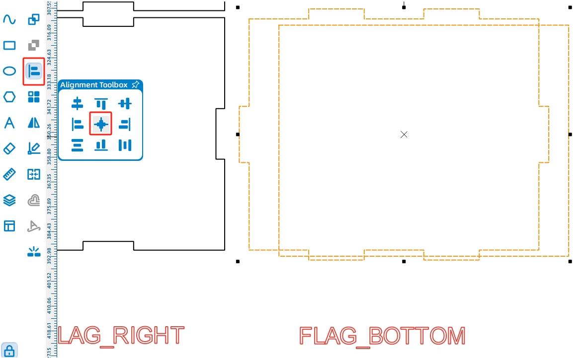
Click on the Selection Tool, press the CTRL key to enter multiple selection mode, select the lower panel and the rectangle drawn in the previous step, then click on the Alignment Toolbox and select Horizontal Center Alignment and Vertical Center Alignment.
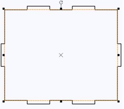
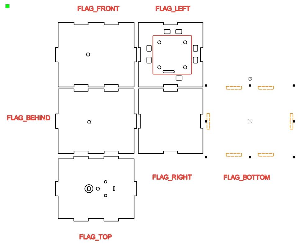
Click on the previously drawn rectangle, and then click on the Subtraction Tool to obtain the six mortise joints between the cabin and the gunwale.
(13) After completing the design of the mortise joints on the gunwale, the bottom mortise joints of the other wooden boards around the cabin need to be changed to tenons to connect the mortise joints on the cabin panel using the mortise and tenon joint method. But what should the size of the tenon be set to?
As there are inevitable losses when laser cutting boards, resulting in differences from the actual length, the laser compensation parameters can be set if the mortise and tenon structure is generated using the “Creation” function built into the laser cutting software. Therefore, when users design the mortise and tenon structure themselves and want to make the joints tighter, manual laser compensation is needed. Taking basswood board as an example, we generally set the laser compensation parameter as 0.3mm. For a mortise joint with a width of 20mm and a height of 3mm, matching it with a tenon of 20.6mm wide and 3mm high can make the structure more secure.
Since the tenon corresponds one-to-one with the mortise joint, the tenon pattern can be modified based on the mortise joint when creating it. Among the six mortise joints generated in the previous step, select two mortise joints in the same horizontal direction, copy them, and align them accordingly.
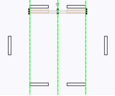
Adjust the dimensions of both rectangles to a width of 20.6mm and a height of 6mm.
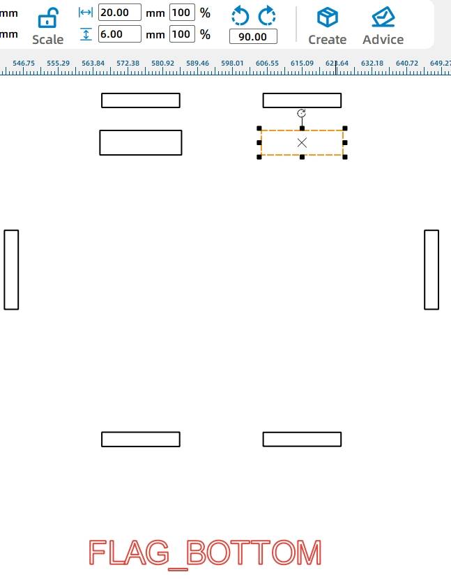
Group the two rectangles and move them to the upper panel. Align the top of the rectangles with the mortise joint and center them, then ungroup them. As you can see, this rectangle is slightly wider than the original mortise joint and extends 3mm below it. This allows us to convert a mortise joint into a tenon.
-.jpg)
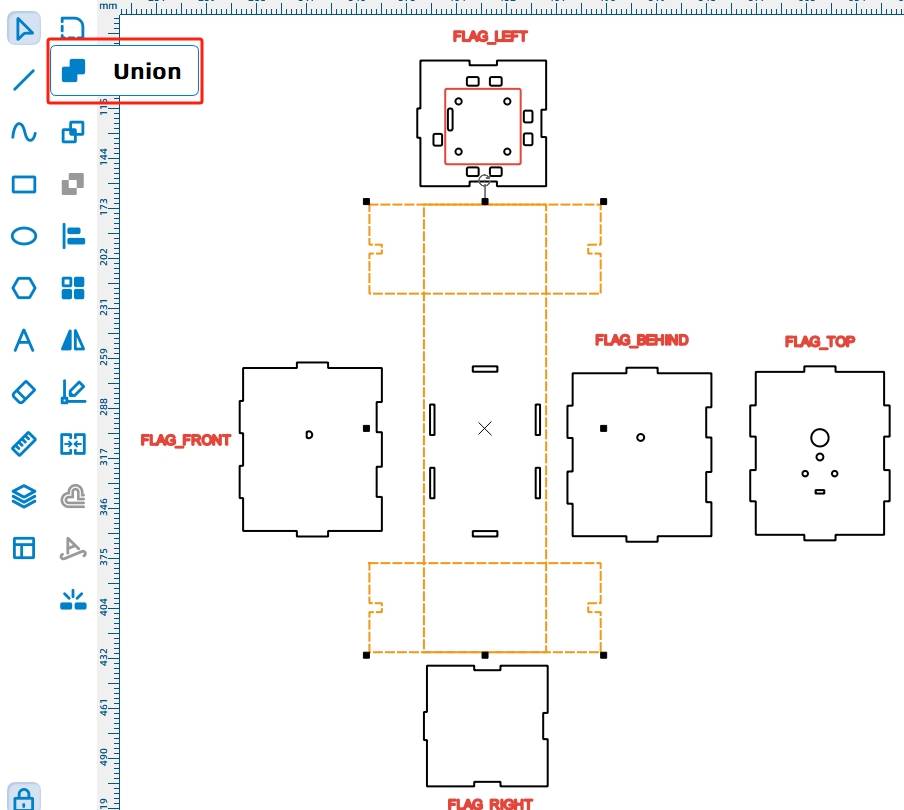
Select the outer contour of the upper panel and the two newly added rectangles, then click on the Union Tool.
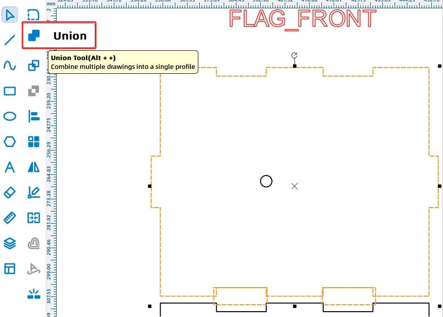
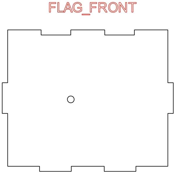
After the Union operation is completed, the original mortise joint on the lower panel has been converted into a tenon, as shown in the figure.
(14) Using the same method, place a rectangle with a width of 20.6mm and a height of 3mm on the mortise joints where the rear panel, left panel, right panel, and lower panel meet.
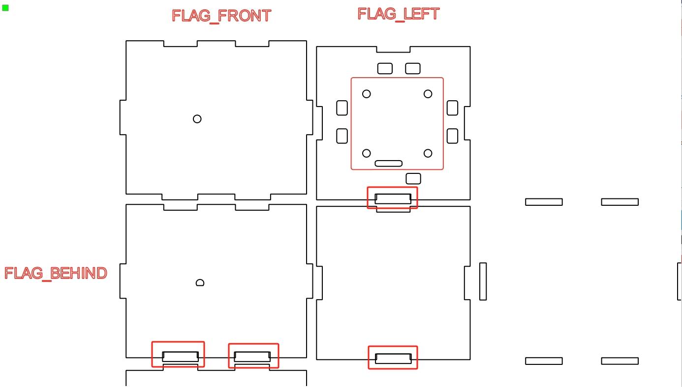
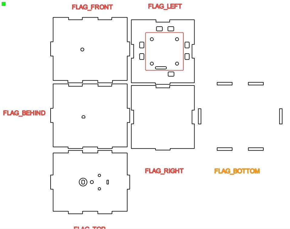
By using the Union operation, you can generate the corresponding tenons. The completed cabin section should look similar to the figure below.
- Drawing the Gunwale
With the cabin design completed, we move on to the design of the gunwale section. The gunwale plays a crucial role in the overall design, supporting the cabin above while connecting to the KT board below to enable the boat to float on the water. Since the paddle wheels are located on both sides of the boat, the gunwale is designed as an “I” shape, with wider ends and a narrower middle.
(1) In the toolbox on the left, select the “Rectangle” tool and draw a large rectangle on the canvas with a width of 100mm and a height of 280mm. Next, draw two smaller rectangles with a width of 160mm and a height of 50mm.
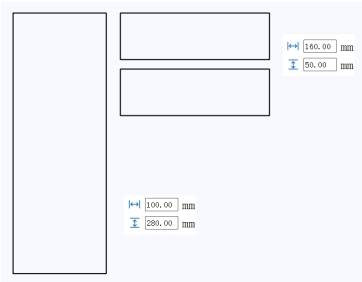
(2) Next, adjust the position of the two smaller rectangles, centering them at the top and bottom of the larger rectangle.
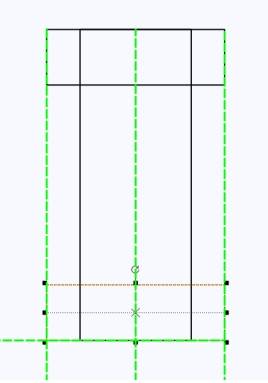
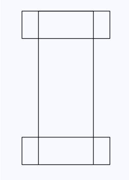
(3) The “I”-shaped gunwale is now complete, as shown in the figure. For ease of subsequent design operations, it’s better to keep the three rectangles separate for easier alignment.
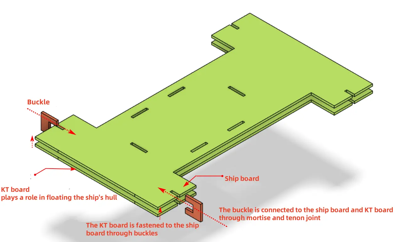
How can we securely attach the KT board to the gunwale? While screwing with nuts and bolts after drilling holes may seem convenient, it can lead to water leakage issues. Therefore, we use a clip system. Specifically, we drill mortise joints of the same size on both the gunwale and the KT board, and then secure them together using a “U”-shaped clip, as shown in the following figure.
(4) To start with the design of the mortise joint, use the “Rectangle” tool to place a rectangle with a width of 10mm and a height of 3mm on the “I”-shaped gunwale.
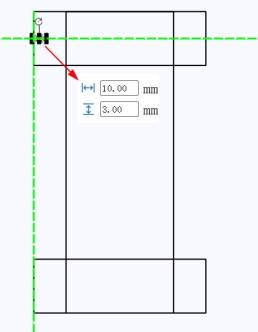
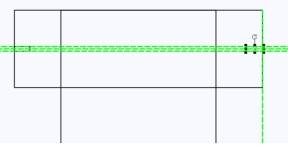
Next, use the “Rectangle” tool to draw another rectangle with a width of 10mm and a height of 3mm, placing it in a symmetrical position to the previous rectangle. The software will display guidelines to indicate whether the two rectangles are horizontally centered and aligned.
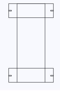
Generate the remaining two mortise joints using the same method. The completed shape should look like the figure below.
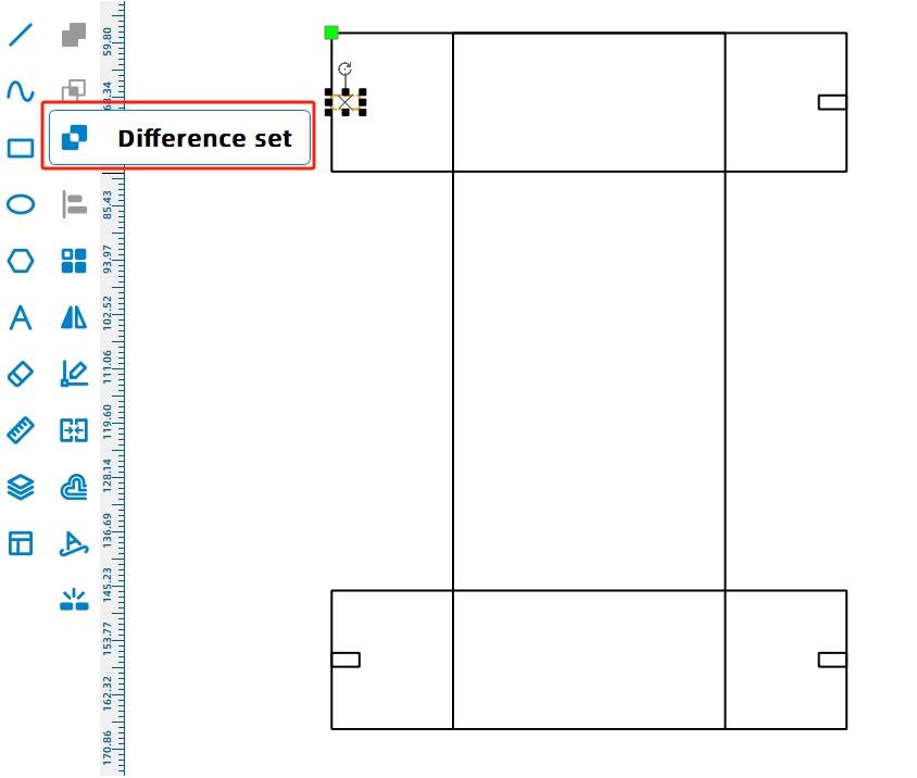
Select one rectangle using the “Selection” tool, and then use the “Difference” tool to create the mortise joint. Repeat this process for the remaining three figures.
With the mortise joints on the gunwale completed, we proceed to design the corresponding clips. The clips’ role is to securely attach the gunwale and the bottom KT board together through mortise-and-tenon joints, enabling the boat to float on the water with the buoyancy of the KT board. As shown in the diagram, two clips need to be placed on each side of the gunwale, totaling four clips.
(5) Select the “Rectangle” tool to create a rectangle with a width of 20mm and a height of 20mm. Then, place a rectangle with a width of 10mm and a height of 9mm horizontally centered on the left side of the larger rectangle.
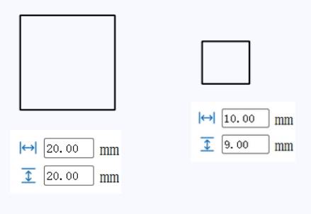
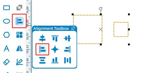
Select the two rectangles, then choose the “Align” tool in the “Toolbox” to left-align and horizontally center-align them.
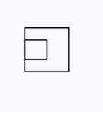
The aligned rectangles appear as follows:
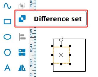
Select the smaller rectangle and click the “Difference” tool to create the clip shape.
Select the clip shape created in the previous step, then choose the “Array” tool in the “Drawing Toolbox”. In the popup settings window, select “Rectangular Array” and configure as shown in the image below. After clicking the “Confirm” button, four identical clips will be generated in the drawing area.
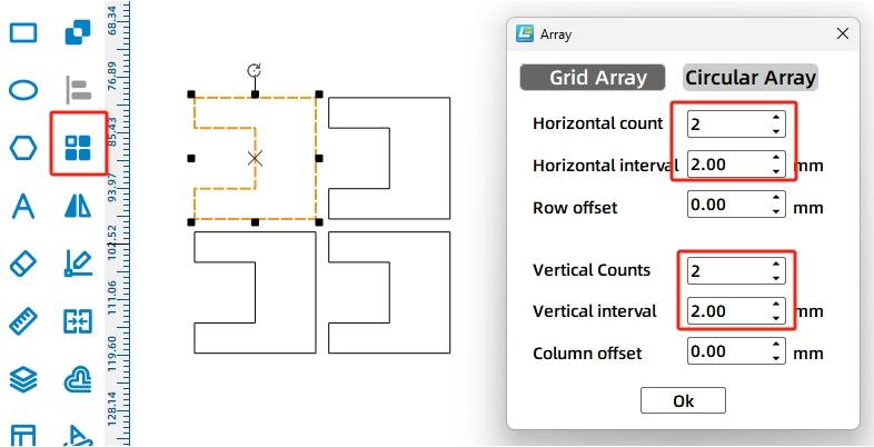
(6) With the clip design completed, the next step is to place the cabin on the deck. As we know from the previous design, there are six tenons at the bottom of the cabin. Here, we can install the cabin on the deck by placing six mortises on the deck. It is worth noting that the sides of the “I” shape are the areas for placing the rotating disks, and the axis of the rotating disk should be on the same line as the center of the boat. Therefore, we need to confirm the center position of the boat first, and then determine the position of the mortises based on the center position. The center position can be determined using guide lines. Hold down the left mouse button on the ruler above the canvas and drag a guide line down to the canvas area. When it reaches the middle of the “I” shape, it will automatically turn green to remind you. You can then release the left mouse button, as shown in the following figure.

Now, we need to align the axle holes of the wooden planks on both sides of the cabin and the axle holes of the rotating disks to the centerline of the deck.
First, rotate the cabin graphic 90 degrees,
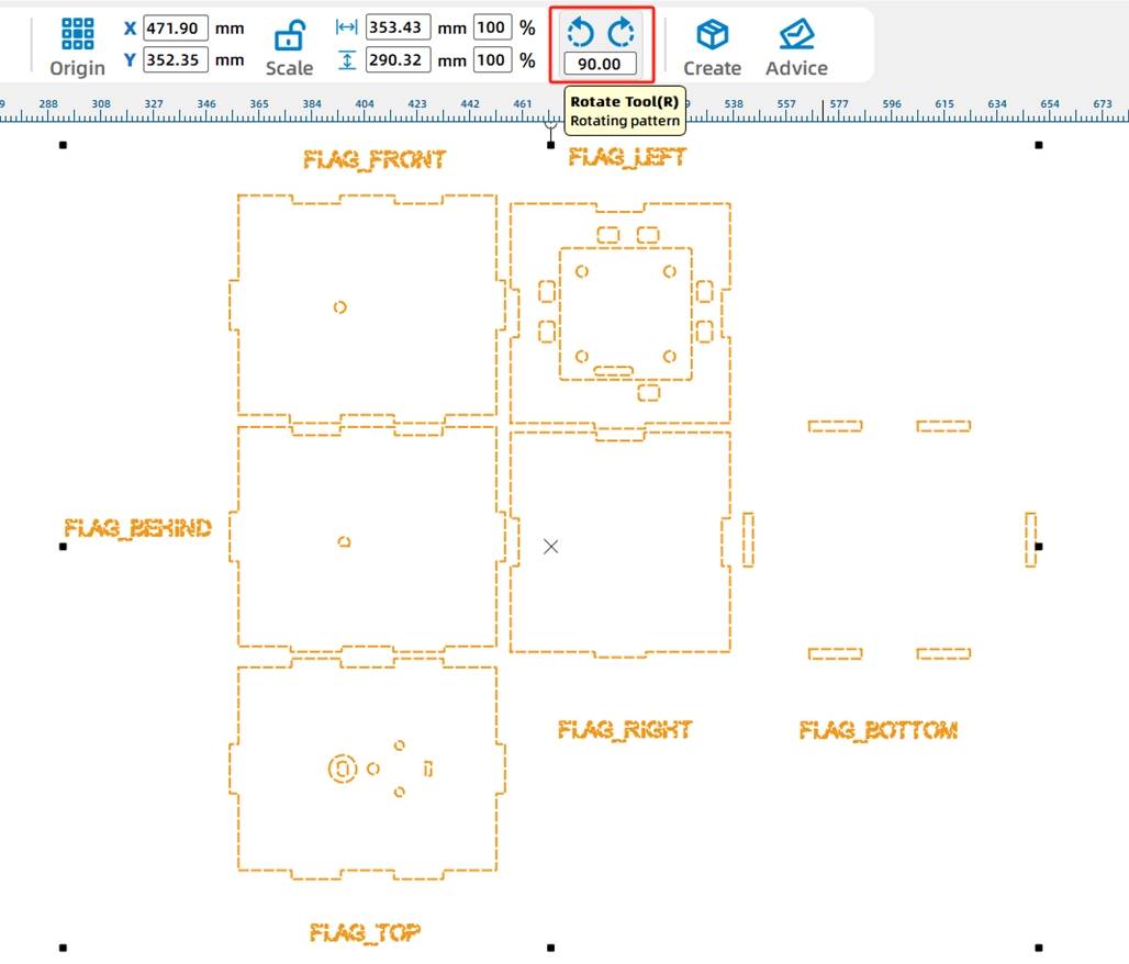
After rotation,
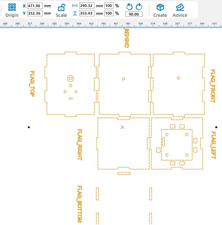
Adjust the position and place it on both sides of the deck, as shown in the image below.
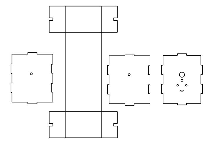
After confirming the relative positions of each component graphic using the centerline, you can move the graphic with six mortises to the “I” shape, aligning it horizontally and vertically centered. The software will automatically display the relative alignment relationship between the graphics with green guide lines, as shown in the following figure.
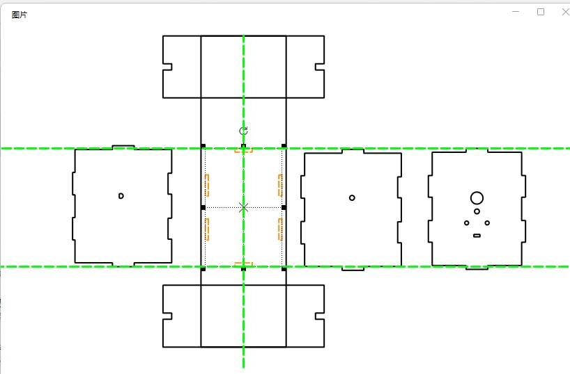
Move the remaining two sides of the cabin to align with the perimeter of the I-shaped graphic in the same manner. The completed graphic will look like the following figure.
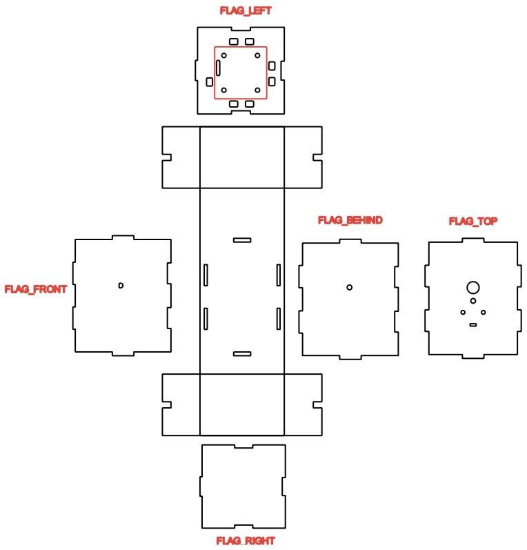
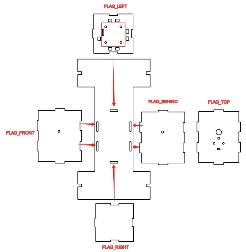
The design of the deck is now complete. When assembling, insert the tenons connecting the front, back, left, and right panels to the deck into the mortises on the deck. The figure below shows the correspondence between the six mortises on the deck and the tenons on each panel.
- Drawing the Paddlewheel
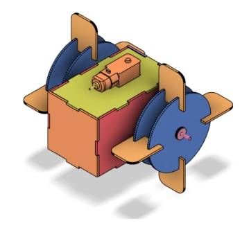
With the deck and cabin completed, we will now proceed to draw the paddlewheel, the propulsion device of the paddle steamer. The appearance of the paddlewheel can be referenced in the following image. The paddlewheel is typically located on the sides or rear of the boat, resembling a wheel with paddle blades attached to its perimeter. When the paddlewheel rotates, the paddle blades push water backward, and the boat is propelled forward by the reaction force of the water.
In this design, the paddle steamer has a paddlewheel on each side. To make the paddlewheel more sturdy and durable, each paddlewheel consists of two rotating disks fastened together with four paddle blades using a mortise and tenon joint.
- Drawing the Rotating Disks
(1) Start by drawing the rotating disks. Since the paddlewheels are on the sides of the deck, the centers of the disks must align with the holes on the sides of the cabin. The disks should be appropriately sized to avoid touching the deck. Place the two previously completed gears on one side of the deck, ensuring their central axis holes align with the deck’s holes using guide lines.
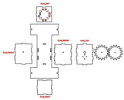
To visualize the positional relationship between the graphics more intuitively, we can also use guide lines for positioning. Utilize the ‘Ellipse Tool’ to draw a circle with a diameter of 100mm and add a circular hole with a diameter of 4mm at its center. Position this circle in alignment with the other centers, as shown in the following figure.
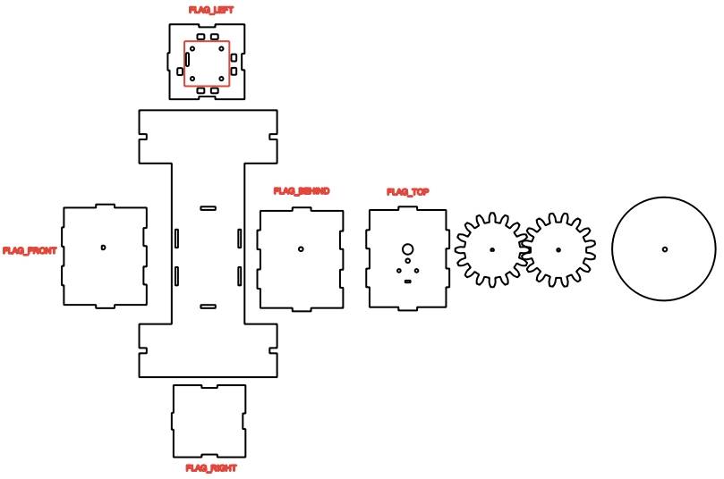
(2) Use the ‘Rectangle Tool’ to draw a rectangle with a width of 3mm and a height of 8mm above the circle. The software’s automatically generated green guide lines can be used to confirm that the hole is centered and tangent to the arc.
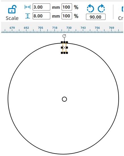
To cut out the mortises for the paddle blades in the rotating disk, the rectangle needs to intersect with the circle of the disk. After placing the rectangle, select the middle adjustment point above the rectangular hole and drag it up slightly to create an intersection between the rectangle and the circle.
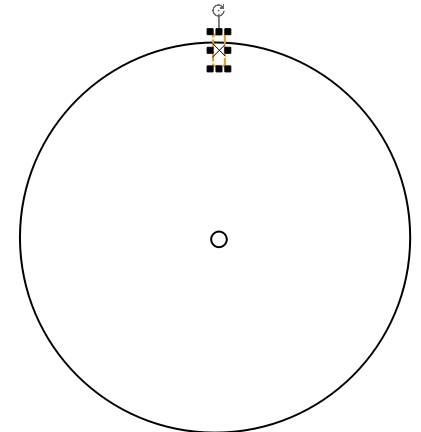
(3) After creating one mortise, as we plan to install four paddle blades on each rotating disk, we need to add three more mortises. This can be achieved using a circular array tool.
First, use the ‘Selection Tool’ to select the circular contour and note down the coordinate values of the center point, as shown in the figure below. The object origin refers to the center position of the object, so the coordinates in the figure represent the center point of the circle.
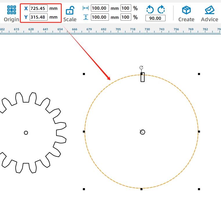
Select the rectangular shape above the circle, then click on the ‘Array’ tool.
(4) In the array settings window that pops up, select the ‘Circular Array’ option, set the step angle to 90 degrees, the number of copies to 4, and set the center point coordinates to the values you just recorded. Do not check the ‘Relative to Center’ option.
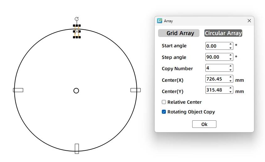
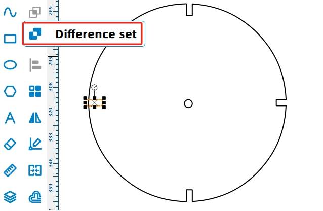
(5) After completing the replication, select each rectangular hole one by one, click on the ‘Difference’ tool to create the mortises, and you will complete the graphic design of one rotating disk.
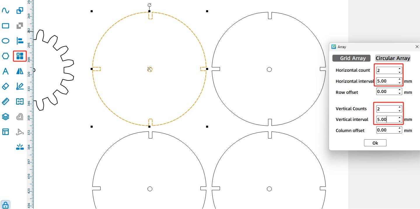
(6) Next, select the entire rotating disk and then choose the ‘Array’ tool from the ‘Toolbox’. Duplicate the disk four times using a rectangular array with the parameters shown in the figure below.
- Drawing the Paddle Blades
After completing the rotating disks, we proceed to the design of the paddle blades. Through observation of the paddlewheel, it can be seen that the paddle blades are fixed to the disks orthogonally. When the disks rotate in a circular motion driven by the TT motor, the paddle blades stir the water to propel the paddlewheel boat. Design can be based on the following figure.
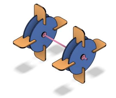
Merely rotating the disks alone cannot propel the boat forward; instead, the paddle blades on the disks must stir the water to generate thrust for forward or backward movement. The paddle blades can be attached to the disks using a mortise and tenon joint.
According to our previous planning, each paddlewheel on both sides requires four paddle blades, so designers need to prepare a total of eight paddle blades.
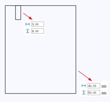
(1) Start by selecting the rectangle tool to draw a rectangle with a width of 40mm and a height of 50mm, as well as a smaller rectangle with a width of 3mm and a height of 8mm.
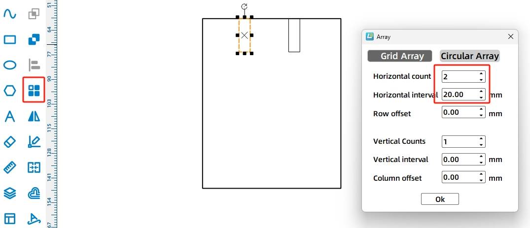
Select the small rectangle and click ‘Array’.
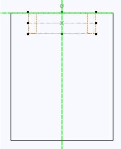
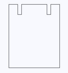
Select both rectangles individually and use the ‘Difference’ tool to create the mortises. The completed graphic will look as shown in the figure.
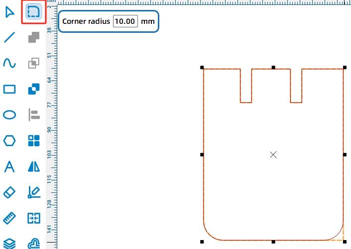
(2) Select the ‘Fillet Tool’ to apply rounded corners to the two right angles at the bottom of the paddle blade, setting the fillet radius to 10mm.
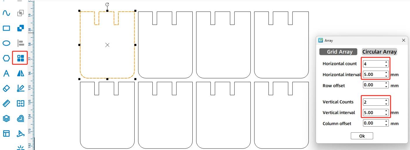
(3) Use the ‘Selection Tool’ to select the paddle blade shape and click on the ‘Rectangular Array’ tool to generate eight paddle blades. The parameters are shown in the figure below.
- Drawing the Axle Housing
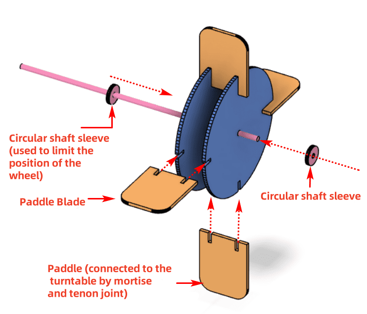
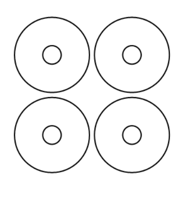
To maintain the position of the rotating disks without deviation, two axle housings can be added on each side of the paddlewheel to achieve a limiting function. Since the diameter of the axle stick is 4mm, to ensure a firmer fit, the corresponding circular hole diameter for the stick needs to be set slightly smaller. The outer diameter is 15mm, and the inner diameter is 3.7mm. The designed drawing is as shown in the following figure.
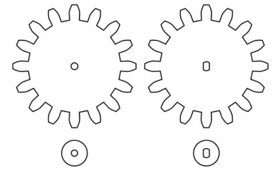
Similarly, for the two gears previously created, two axle housings also need to be made for limiting purposes. The outer diameters remain 15mm, while the inner diameters are circular holes corresponding to the TT motor’s shaft hole and a circle with a diameter of 3.7mm.
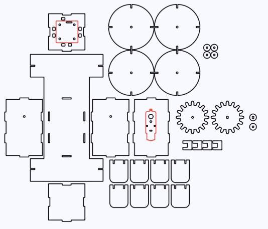
All the design drawings for the parts required by the waterborne pleasure boat are now complete, as shown in the following figure.
After completing the drawing designs, they can then be processed with laser cutting.
Laser Processing
Check and confirm the speed and power settings for the tracing and cutting steps in the processing workflow. Click on the “Simulate Fabrication” option to further review and confirm the sequence of processes such as tracing and cutting. Finally, import the file into the laser cutter to complete the cutting of the work.
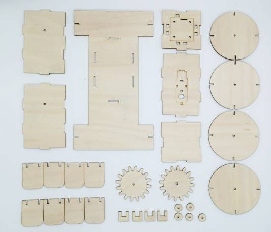
Model Assembly
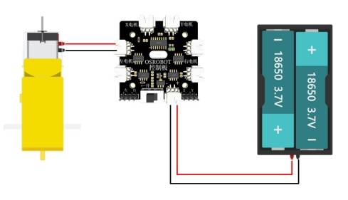
Circuit Wiring
Once the waterborne pleasure boat is fully assembled, we will connect the circuit according to the wiring diagram shown in Figure 6-64, and the boat can then be launched for operation.
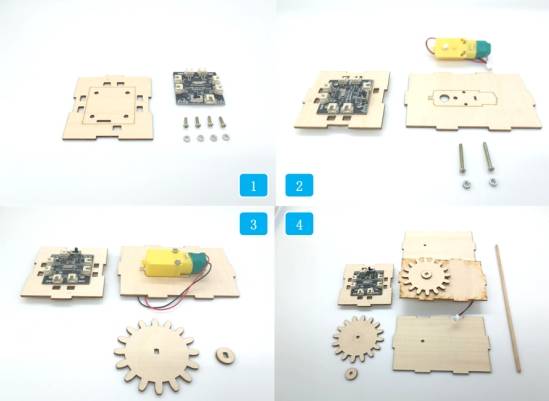
Structural Assembly
Next, we’ll assemble the processed parts.
Steps:
1, 2: Mount the receiver board and TT motor onto the hull using M3 screws and nuts.
3: Take out the gear with a TT-compatible axle hole and its housing, and secure them onto the TT motor axle.
4, 5: Take out the gear with a circular axle hole, its housing, a 4mm diameter wooden stick, and the hull’s two perforated side panels. Pass the stick through the panels, gear, gear housing, and the opposite panel in sequence.
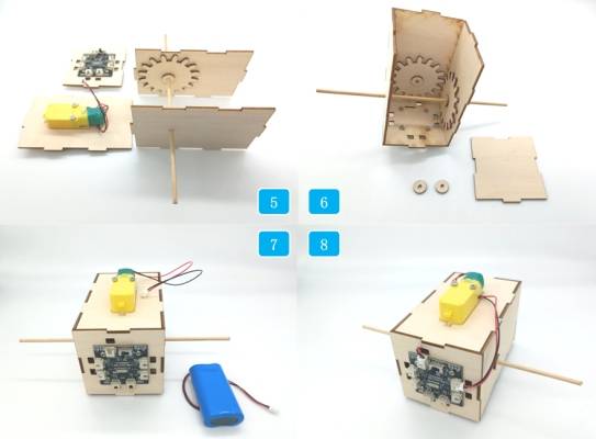
Step 6: Connect the hull panel with the receiver board and TT motor to the structure completed in Step 5.
Step 7: Take out the two paddlewheel axle housings and the remaining hull panel. Install them onto the wooden stick and hull structure respectively. Pass the battery through the preset hole on the panel from inside the hull.
In Step 8, connect the TT motor and power wires to the “Left Motor” and “Power” interfaces of the receiver board, completing the hull construction.
Step 9: To assemble the paddlewheel structure, first take out the components of the paddlewheel and insert the four paddle blades into the notches of two disks. Repeat the same process to complete the assembly of the other paddlewheel.
Steps 10 and 11: Place the paddlewheel clips and paddlewheels onto the protruding wooden stick of the hull. During installation, position each paddlewheel between the two axle housings. By adjusting the position of the axle housings, you can optimize the paddlewheel’s alignment.
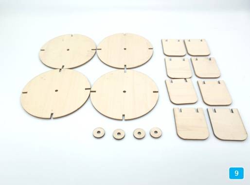
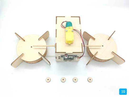
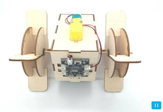
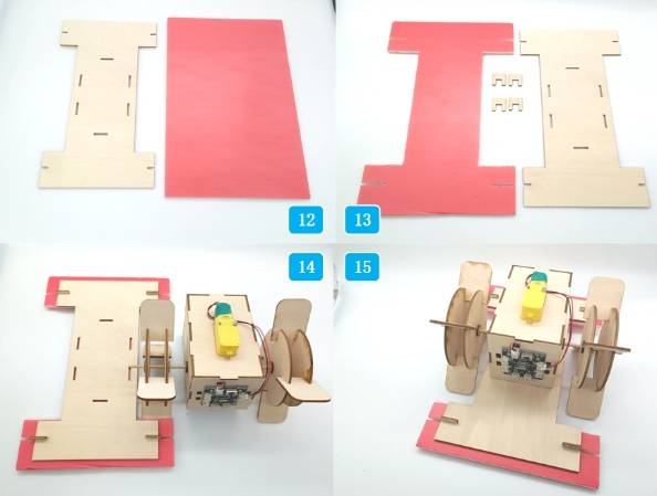
In Step 12, take out the deck parts and the KT board. Place the deck parts on the KT board and use a marker to outline the notch positions and the openings on both sides. Use a knife to cut away the excess parts. Then, take out the deck clips and combine the deck and KT board. Finally, attach it to the previously completed hull section using the mortise and tenon joints on the deck. The final completed product is shown in Step 15.
Summary
In the construction of this waterborne pleasure boat, vertical gear transmission is a key concept that we need to grasp. It refers to the use of two gears meshing perpendicularly to each other, where the rotating gear drives another gear on a vertical plane, thus achieving power transmission between different planes. In the design process, the union function, alignment function, and auxiliary lines were used multiple times. Mastering these modeling techniques can effectively help you design more creative works.
The waterborne pleasure boat project is the only aquatic attraction in the amusement park, attracting players from Planet M to rush for a thrilling experience. However, the amusement park also boasts many other exciting attractions. Let’s continue exploring with the designers!
Thought Expansion
In this project, the designers installed a paddlewheel on each side of the paddlewheel boat and used a dual-shaft motor to propel the model forward. But can we try a different approach? Could we install just one paddlewheel at the stern of the boat? Interested readers can experiment with this idea.
Browse Thunder Laser
Bolt >


.png) International
International
 United States
 Brasil
 Canada
 Costa Rica
 Česká
Česká
 Ελλάδα
 Polska
 Ireland
 Portugal
 Lietuva
 Россия
 Deutschland
 Britain
 Україна
 France
 Sverige
 Italia
 Norway
 Denmark
 Romania
 한국
한국
 中国
中国
 ประเทศไทย
 中国香港
中国香港
 Israel
 中國臺灣
中國臺灣
 India
India
 پاکستان
 پශ්රී ලංකා
 ジャパン
ジャパン
 Australia
 New Zealand
 South Africa