Origin of the Project

Now, the responsible party of Planet M hopes to have a unique billboard to attract tourists for the amusement park. The designers are brainstorming and pooling ideas. Let’s work together with the designers to create an amusement park billboard.
Determining the Design Plan
Observation and Analysis
What are the common billboards in bus stops, subway stations, shopping malls, and supermarkets like? As shown in Figure 7-2. This time, we aim to design a unique billboard. The billboards we usually see are static. If the billboard we create can move left and right, it will be very eye-catching. To achieve the movement of the billboard, we need to incorporate a motor, and luckily, the manufacturing facility has OSROBOT open-source robot remote control kits available for us to use.

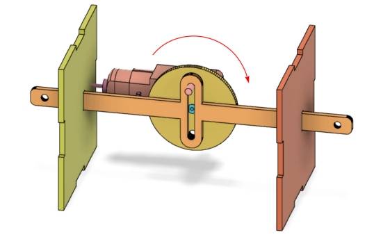
The movement trajectory of a motor is usually circular, so a motor alone cannot achieve the left-right movement of a billboard. We need to design a structure that converts the circular motion into a reciprocating left-right motion. This is the focus of our current lesson, as shown in the following figure.
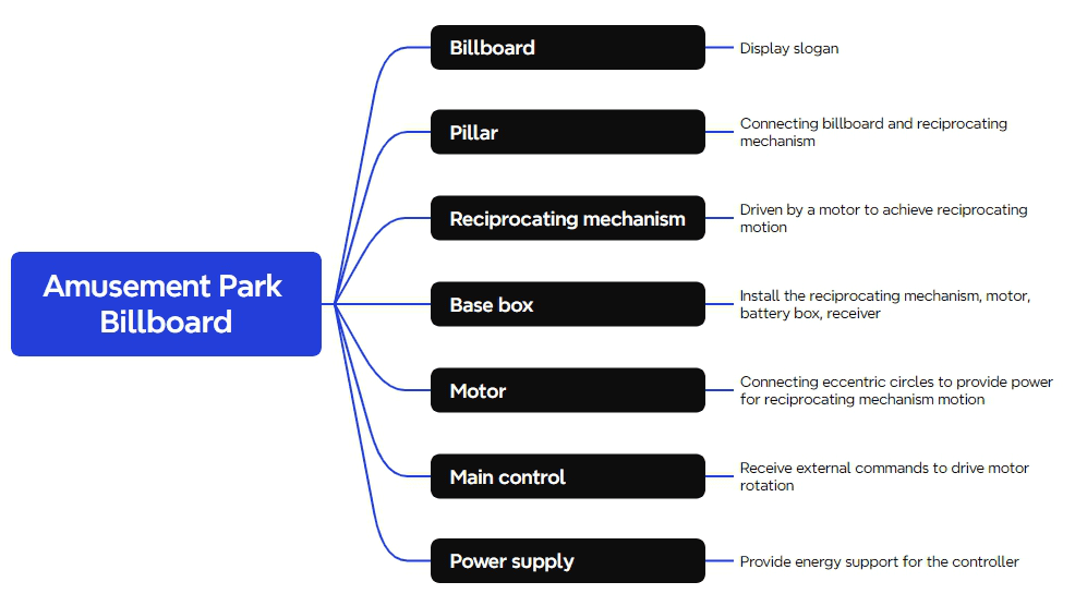
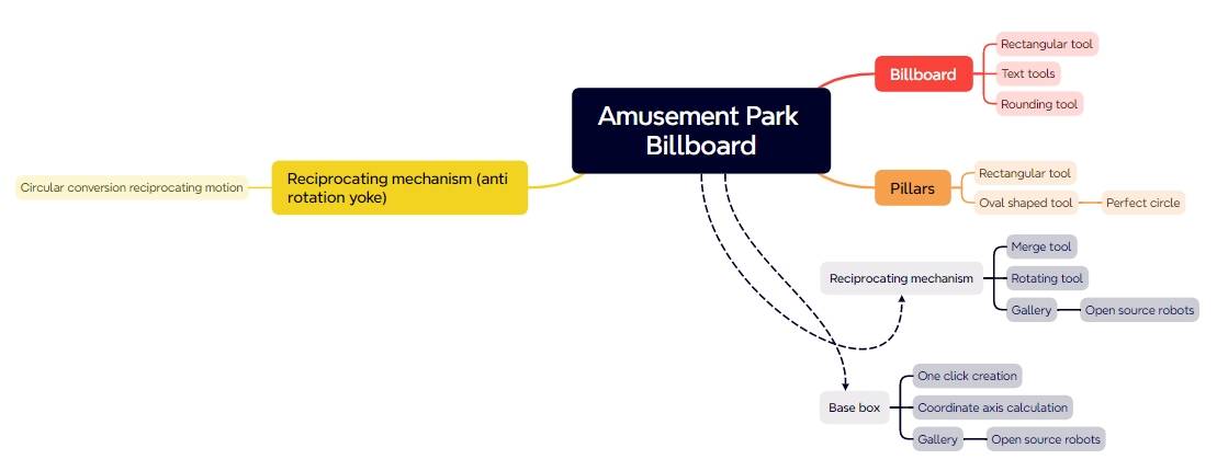
After the above analysis, we can break down the amusement park billboard into the following components, as shown in the following figure.
Material List
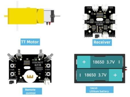
There are a total of seven items in the material list for this project, as shown in the following figure.
Number
Item
Quantity
1
2.4G Remote Controller (with batteries)
1
2
2.4G Receiver
1
3
TT Motor (1:120)
1
4
18650 Battery (with wires)
1
5
Basswood Laminate (40cm60cm3mm)
1
6
M3/M4 Screws and Nuts
Several
Number | Item | Quantity |
1 | 2.4G Remote Controller (with batteries) | 1 |
2 | 2.4G Receiver | 1 |
3 | TT Motor (1:120) | 1 |
4 | 18650 Battery (with wires) | 1 |
5 | Basswood Laminate (40cm60cm3mm) | 1 |
6 | M3/M4 Screws and Nuts | Several |
Structural Design of the Project
After selecting the materials, we will now proceed to designing the exterior structure of the amusement park billboard.
Creating the Parts List
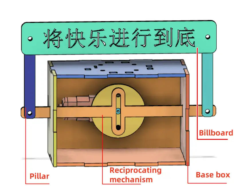
Based on the observation and analysis of the amusement park billboard, we can determine the structural parts that need to be designed for the project. The structural parts are listed in the following Table, which consists of 4 main components.
Part No. | Part Name | Quantity | Function |
1 | Billboard | 1 | Displays advertisements |
2 | Supports | 2 | Connects the billboard to the reciprocating mechanism |
3 | Reciprocating Mechanism | 1 | Driven by the motor to achieve reciprocating motion |
4 | Base Enclosure | 1 | Houses the reciprocating mechanism, motor, battery pack, and receiver |
Laser Modeling
After determining the parts list, it’s now time to start laser modeling.
- Drawing the Billboard
Common billboards are rectangular, so we’ll use the rectangular tool in LaserMaker software to design the billboard.
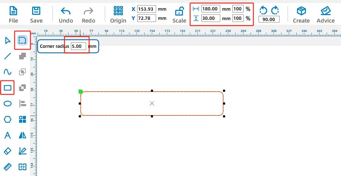
(1) Select the “Rectangle Tool” from the drawing toolbar and draw a rectangle with a width of 180mm and a height of 30mm. For aesthetics, modify the rectangle’s sharp corners to rounded corners using the “Rounding Tool” and set the rounding radius to 5mm. Click on each corner of the rectangle to set the rounded corners individually. As shown in the following figure.
(2) After outlining the billboard, two circular holes with a diameter of 4mm need to be designed to connect with the supports.
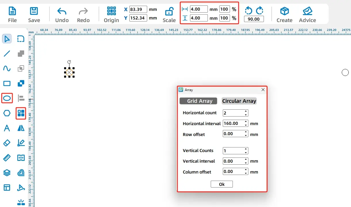
Select the “Ellipse Tool” from the drawing toolbar and draw a perfect circle with a width and height of 4mm on the canvas. Then, select this circle with the mouse and choose the “Array Tool” from the menu toolbar. In the pop-up rectangular array parameter settings, set the horizontal count to 2, horizontal spacing to 160mm, offset between rows to 0, and vertical count to 1. After confirming, the second circle will be replicated. As shown in the following figure.
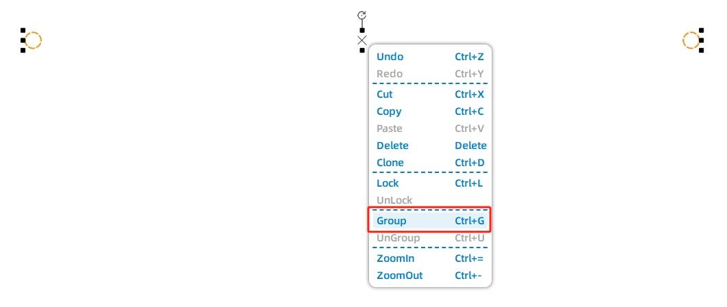
(3) Use the keyboard shortcut Ctrl+G or the right-click grouping function to group the two circles together. As shown in the following figure.
(4) The most crucial part of the billboard is the “slogan.” Next, we’ll use the “Text Tool” to add a slogan to the billboard.
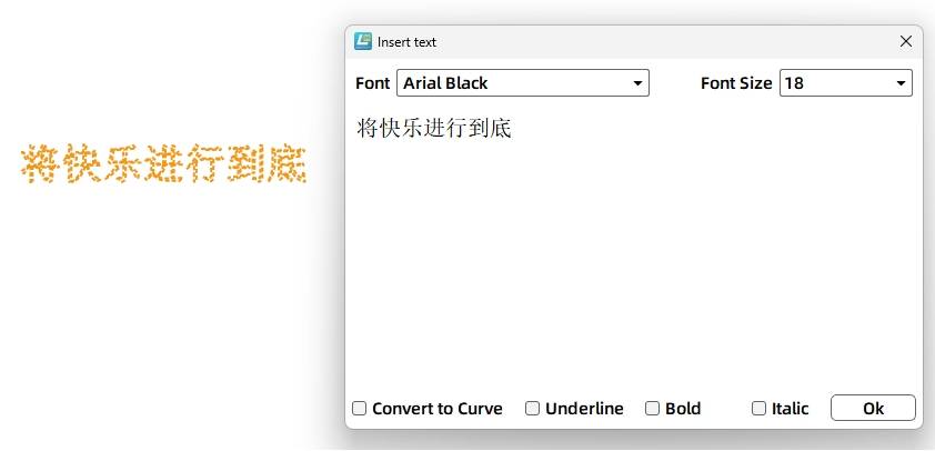
Select the “Text Tool” from the drawing toolbar, double-left-click on the canvas to create a text box, enter the desired text content, such as “Enjoy the Joy to the Fullest,” set the font to “SimSun,” font size to “Wuhao,” and click “OK.” The “slogan” design is complete, as shown in the following figure.
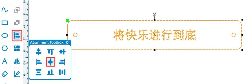
(5) Now, select all the completed shapes (rectangle, circles) and text using a bounding box, then click on the “Alignment Toolbox” in the drawing toolbar. Choose both horizontal and vertical centering alignment. Once done, the billboard design is complete. As shown in the following figure.
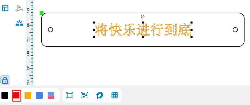
(6) In the lasermaker software, black is typically the default for cutting (where the material is fully cut through), while red is the default for engraving (which leaves a mark on the surface of the material). Since the slogan only needs to be presented on the surface of the material, we’ll use the red engraving layer. Select the text “Enjoy the Joy to the Fullest” and click the lower-left corner of the canvas to set it to the “Red Layer.” As shown in the following figure.
- Drawing the Supports
With the billboard design complete, we now need to support it vertically, requiring two rectangular supports. For aesthetic purposes, we’ll also apply rounded corners to both rectangles.
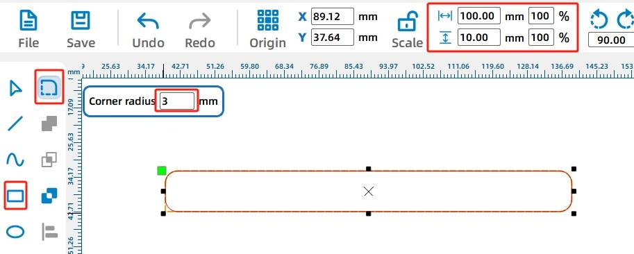
(1) Using the “Rectangle Tool” in the drawing toolbar, draw a rectangle on the canvas with a width of 80mm and a height of 10mm. Then, select the “Rounding Tool” and set the rounding radius to 3mm. Click on each corner of the rectangle to apply the rounded corners one by one. As shown in the following figure.
(2) Next, we’ll create two holes with a diameter of 4mm in the support to connect the billboard and the reciprocating sliding rod.
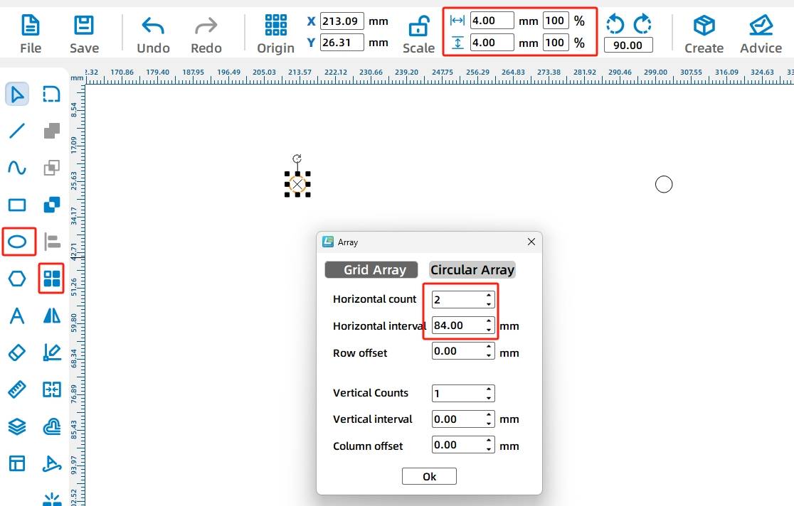
Using the “Ellipse Tool” in the drawing toolbar, draw a circle with a width and height of 4mm. Then, select the “Rectangular Array Tool” to create an array of the circle. Set the horizontal count to 2, horizontal spacing to 66mm, offset between rows to 0, and vertical count to 1. Click “OK” to obtain the second identical circle. As shown in the following figure.
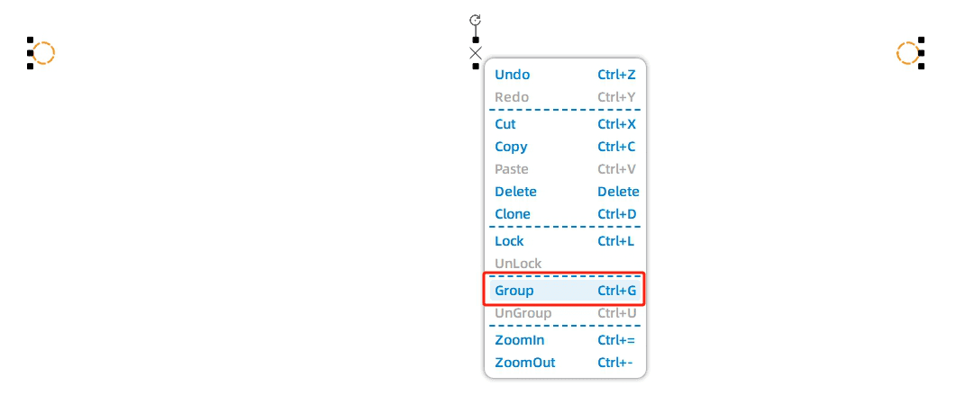
Then, group them using the keyboard shortcut Ctrl+G or the right-click grouping function. As shown in the following figure.
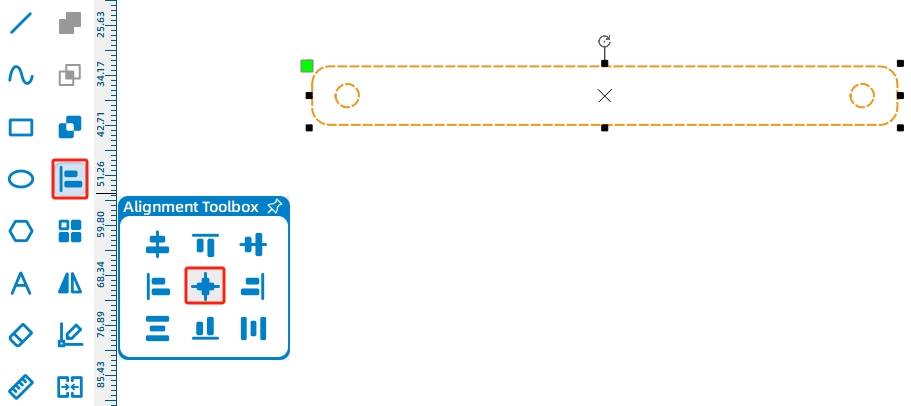
After the hole positions are designed, we need to center the circular holes within the rectangle. Using the “Selection Tool,” select both the rectangle and the circular holes. Then, click on the “Alignment Tool” in the drawing toolbar and choose horizontal and vertical centering to center the circular holes. As shown in the following figure.
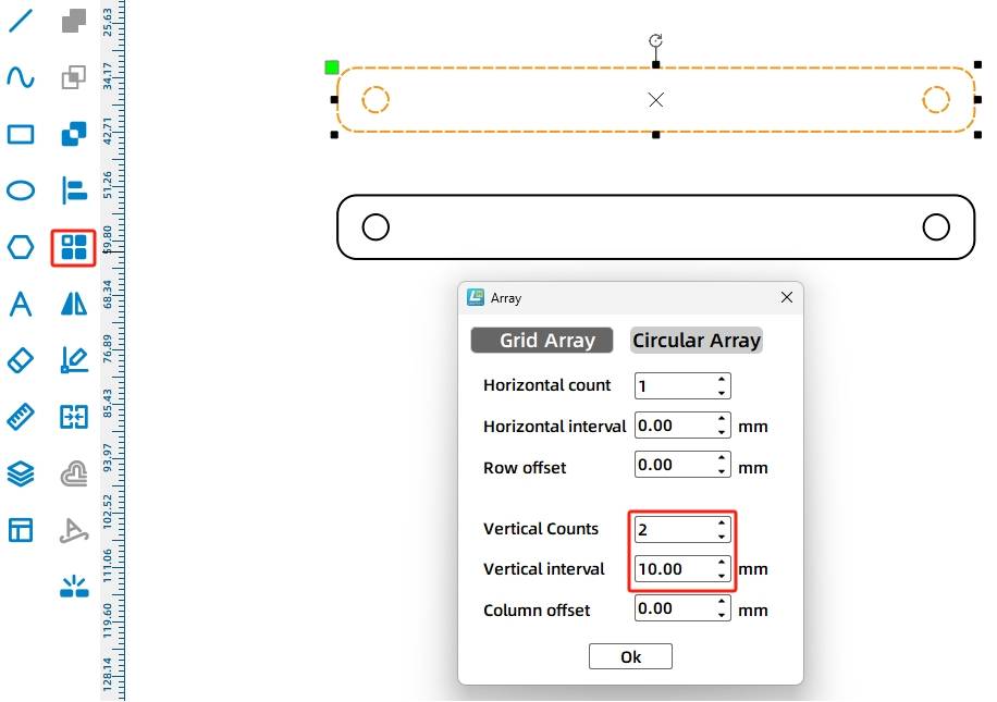
(5) Next, select the “Rectangular Array Tool” to create an array of the shape. Set the horizontal count to 1, vertical count to 2, vertical spacing to 20mm, and offset between columns to 0. Click “OK” to obtain the second support. As shown in the following figure.
(6)With the support design complete, we move on to the most crucial part of this project – the reciprocating mechanism, also known as the anti-rotation yoke. It consists of three parts: a disk, an anti-rotation slot, and a sliding rod. As shown in the following figure.
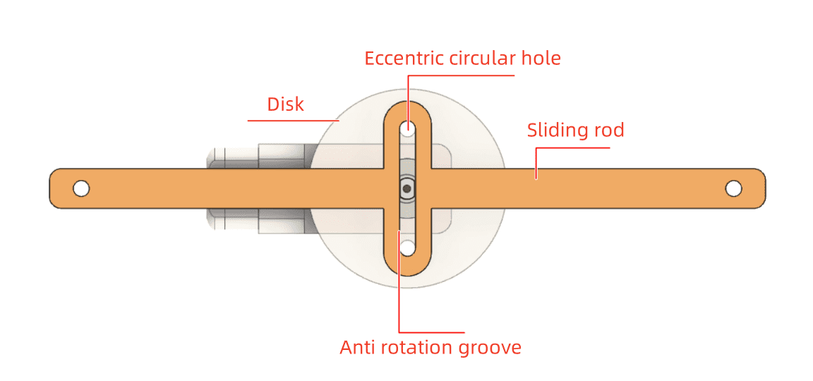
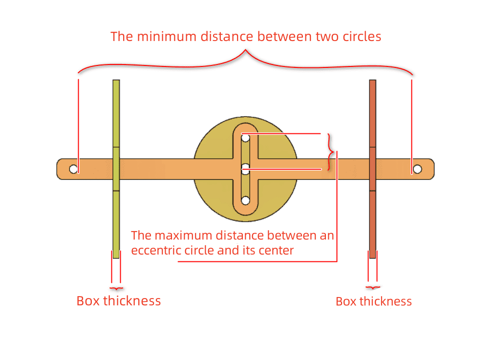
To achieve the desired effect of the billboard moving back and forth regularly, the anti-rotation slot structure is crucial. During the movement of the anti-rotation yoke, the slot performs a reciprocating motion as the eccentric mechanism of the circle rotates. The length of the slot depends on the maximum straight-line distance from the center of the circle to the eccentric hole. The slot length is twice the maximum straight-line distance, while the slot width is determined by the diameter of the eccentric hole. The outer contour of the anti-rotation yoke should be larger than the inner slot.
- Drawing the Anti-Rotation Slot of the Reciprocating Mechanism
(1) Select the “Ellipse Tool” from the drawing toolbar to draw a circle with a width and height of 4mm. Then, use the “Rectangular Array Tool” to replicate the circular holes. Set the horizontal count to 2, horizontal spacing to 26mm, offset between rows to 0, and vertical count to 1. As shown in the following figure.
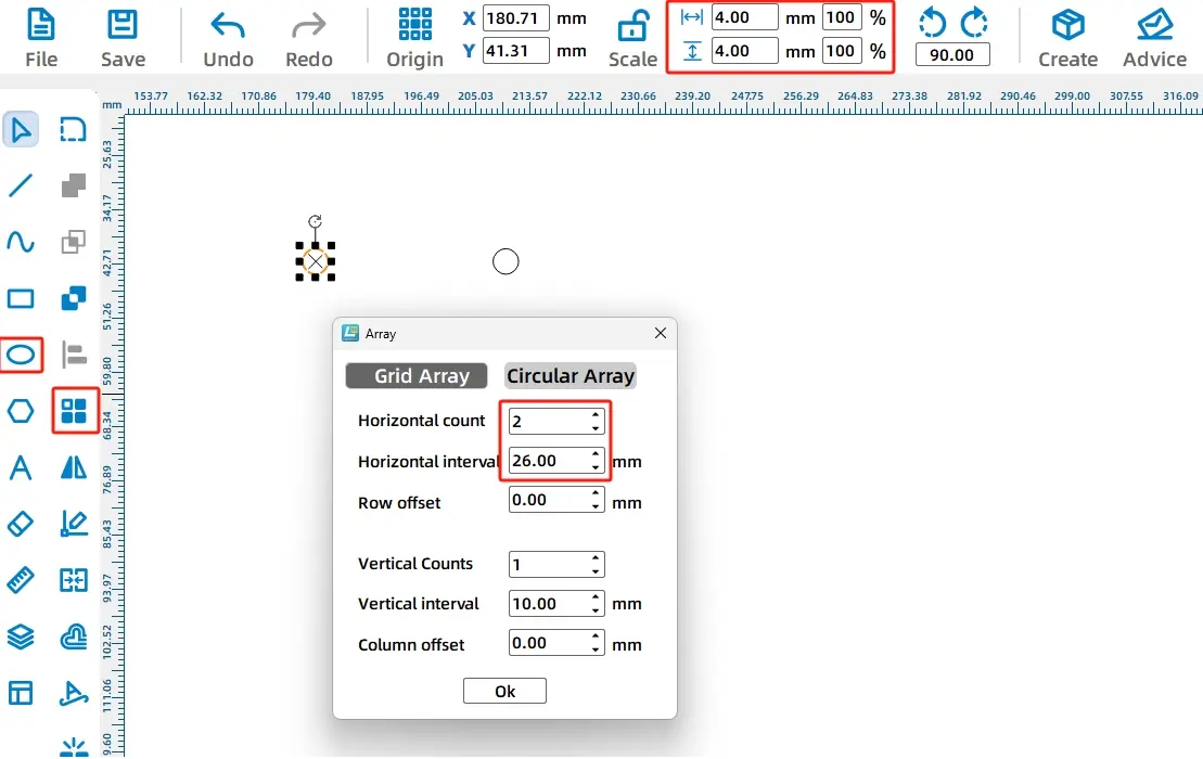
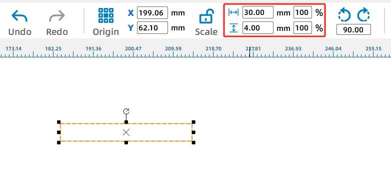
Next, a 30mm wide and 4mm tall rectangle needs to be merged with two circles to form the anti-rotation slot. From step ①, we know the circle radius is 2mm and the minimum spacing between the two circles is 26mm, thus the distance between the two circle centers is 30mm, determining the length of the rectangle. Since the protrusion of the eccentric circle is replaced by a 4mm diameter screw, the height of the rectangle is set to 4mm.
(2) Select the “Rectangle Tool” from the drawing toolbar to draw a rectangle with a width of 30mm and a height of 4mm. As shown in the following figure.
(3) Next, to combine the rectangle with the two circles to form the anti-rotation slot, we need to align them first.
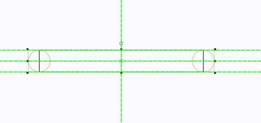
Using the “Selection Tool,” select both circles simultaneously and then drag and move the circles onto the rectangle, referencing the alignment guides to vertically and horizontally center-align the circles with the rectangle. As shown in the following figure.
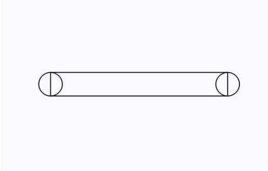
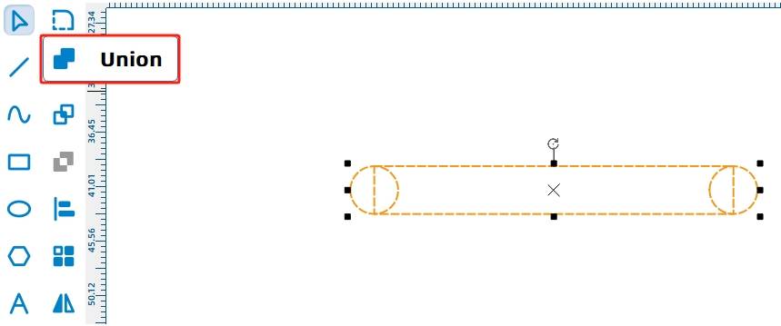
(4) Select both the rectangle and the two circles that were previously drawn, and then click on the “Union Tool” in the drawing toolbar to merge the shapes, combining the circular holes and the rectangle into a single entity, as shown in the following figure.
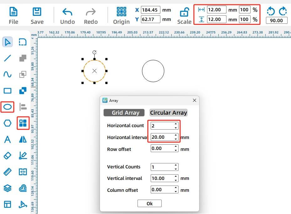
(5) After drawing the inner anti-rotation slot of the yoke, we need to create its outer contour. The drawing method is similar, but the dimensions of the outer contour should be larger than the inner contour. Use the “Ellipse Tool” to draw a rectangle with a width and height of 12mm. Then, select the “Rectangular Array Tool” to create a circular array with a horizontal count of 2, horizontal spacing of 20mm, offset between rows of 0, and vertical count of 1. As shown in the following figure.
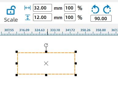
(7) Select the “Rectangle Tool” from the drawing toolbar to create a rectangle with a width of 32mm and a height of 12mm. As shown in the following figure.
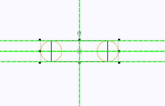
(8) Use the “Selection Tool” to select both circles simultaneously, then drag and move the circles onto the rectangle. Align the circles vertically and horizontally centered with the rectangle using the alignment guides. As shown in the following figure.
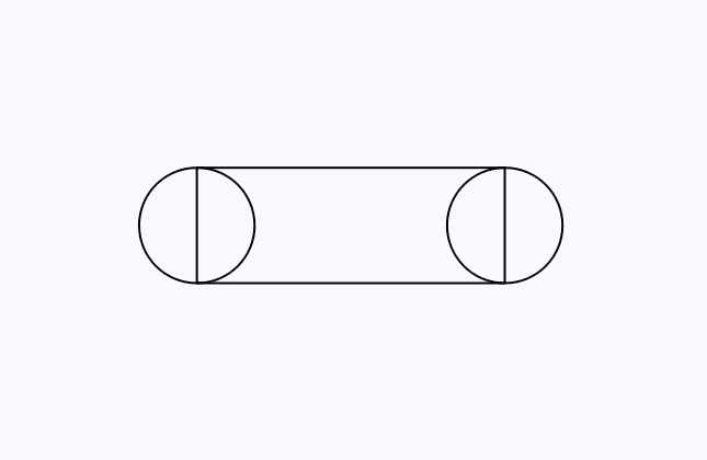
(9) Next, merge them together. Select the drawn rectangle and two circles simultaneously, and then use the “Union Tool” to combine the shapes. This completes the outer contour of the anti-rotation yoke, as shown in the following figure.
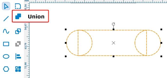
(10) Now, align the outer contour and inner anti-rotation slot of the anti-rotation yoke centrally. Use the “Selection Tool” to select both the inner and outer contours simultaneously, then use the “Alignment Tool” to choose horizontal and vertical centering alignment. Align the inner and outer contours centrally, as shown in the following figure.
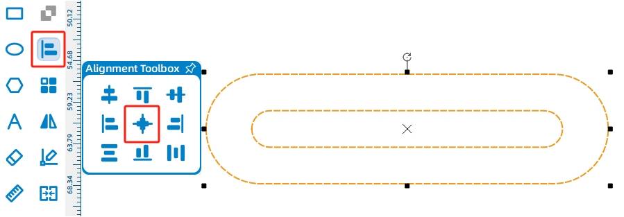
The reciprocating mechanism’s slide rod and the anti-rotation yoke combine to form an integral unit, primarily achieving left-right reciprocating motion following the trajectory of the anti-rotation yoke. At both ends of the slide rod, a circular hole with a diameter of 4mm is drawn to fix the billboard support. Since the slide rod moves back and forth horizontally inside the housing, the minimum spacing between the two holes must be greater than or equal to the maximum distance between the eccentric circle and its center plus twice the thickness of the housing plate. After calculations, the spacing between the two holes here is set to 160mm, as shown in the following figure.
(1) Select the “Ellipse Tool” from the drawing toolbar to draw a circle with a width and height of 4mm. Then, choose the “Rectangular Array Tool” to create a circular array with a horizontal count of 2, horizontal spacing of 160mm, offset between rows of 0, and vertical count of 1. As shown in the following figure.
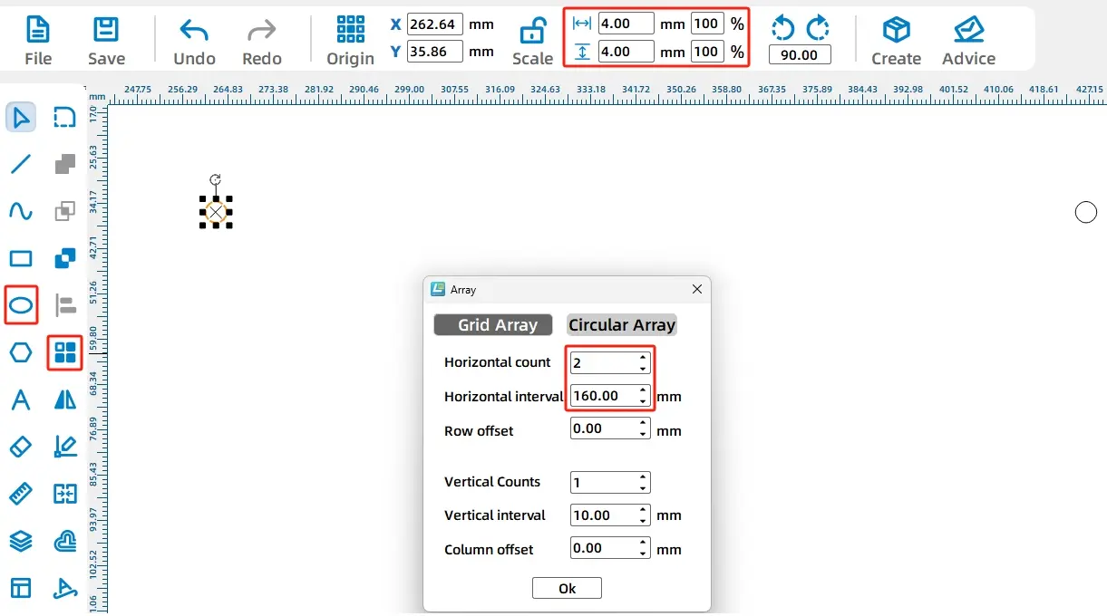
(2) With the two circular holes for the slide rod completed, we now proceed to design the main body of the slide rod.
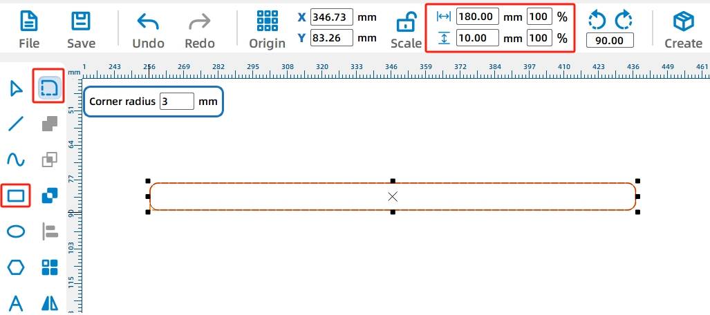
Select the “Rectangle Tool” from the drawing toolbar to draw a rectangle with a width of 180mm and a height of 10mm. Then, choose the “Corner Rounding Tool” and set the rounding radius to 3mm. Click on each of the four right angles of the rectangle to apply the rounding individually. As shown in the following figure.

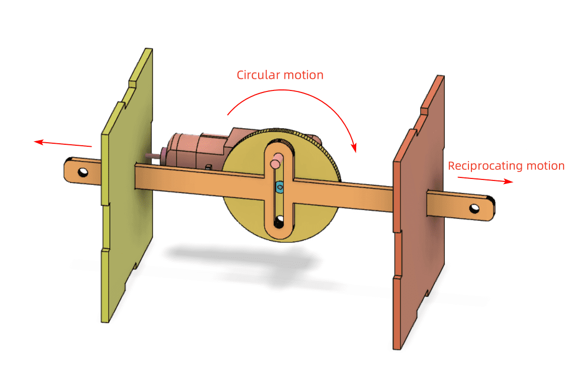
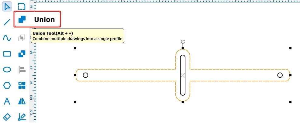
As seen in the following figure, the rotation of the eccentric circle drives the reciprocating motion of the slide rod and anti-rotation yoke. This necessitates the design of the anti-rotation yoke and slide rod as a single unit.
(4) First, adjust the anti-rotation yoke to a vertical position. Use the Selection Tool to select the anti-rotation yoke and rotate it 90° using the Rotate Tool. Then drag the “anti-rotation yoke” onto the “slide rod” and align it vertically and horizontally centered with the slide rod using the alignment guides. As shown in the following figure.
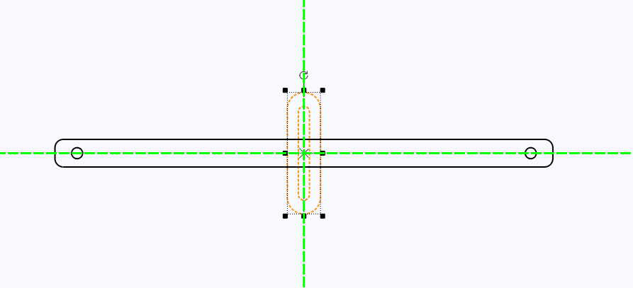
(5) Next, merge the anti-rotation yoke and slide rod. Use the Selection Tool to select the outer contours of both the slide rod and anti-rotation yoke (note to select only the outer contours). Then, click on the Union Tool in the drawing toolbar to combine the selected shapes, as shown in the following figure.
- Drawing the Disc for the Reciprocating Mechanism
With the slide rod design completed, we now proceed to design the disc for the reciprocating mechanism.
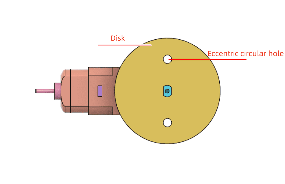
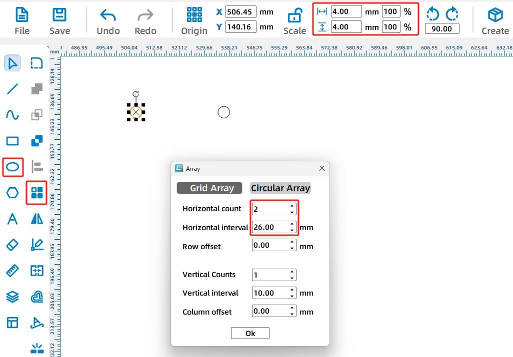
(1) As shown in the following figure, we design two eccentric circular holes in the disc. By connecting one of these holes with the anti-rotation slot using screws, we can convert the circular motion of the eccentric circular hole into reciprocating motion of the slide rod. Use the “Ellipse Tool” to draw a circle with a width and height of 4mm as the eccentric circle. Then, select the “Rectangular Array Tool” to duplicate the second eccentric circle, setting the horizontal count to 2, horizontal spacing to 26mm, offset between rows to 0, and vertical count to 1. As shown in the following figure.
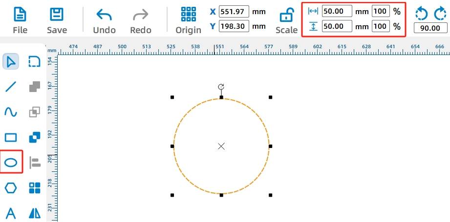
(2) Next, we need to place the two eccentric circles within a disc with a diameter of 50mm. Select the “Ellipse Tool” from the drawing toolbar and draw a circle with a width and height of 50mm. As shown in the following figure.
Dragging out the TT hole pattern combines the three graphics to ultimately connect with the TT motor shaft.
(3) Since the disc is driven by a TT motor, a TT motor shaft hole needs to be added to the center of the disc. Use the Selection Tool to drag out the disc and the two eccentric circles. Then, drag the “TT Hole” pattern from the “Open-Source Robot Hardware” library onto the canvas, as shown in the following figure.
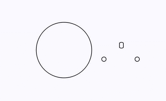
(4) Use the Selection Tool to drag the “TT Motor Shaft Hole” and “Eccentric Circular Holes” onto the “Disc,” aligning them vertically and horizontally centered with the “Disc” using alignment guides. As shown in the following figure.
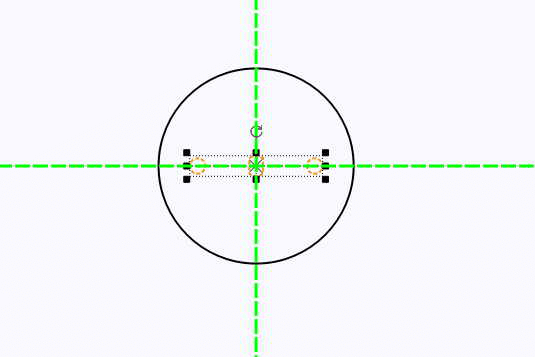
- Drawing the Circular Spacers for the Reciprocating Mechanism
To ensure smooth rotation of the disc, two spacers need to be installed in the TT motor to prevent the motor shaft from protruding and blocking the anti-rotation slot.
The TT motor shaft length is approximately 8.5mm, while the actual thickness of a 3mm basswood board is around 2.8mm. Therefore, two circular spacers are required for the TT motor shaft.
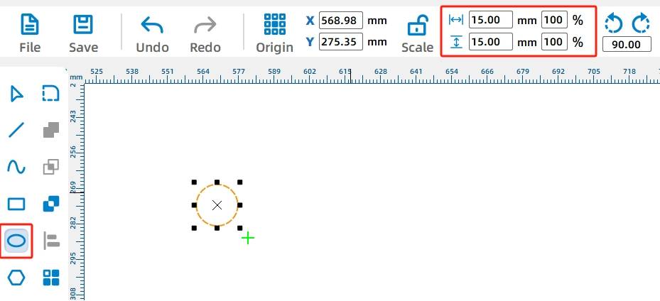
(1) Now let’s design the spacers. Use the Ellipse Tool to draw a circle with a width and height of 15mm on the canvas. As shown in the following figure.
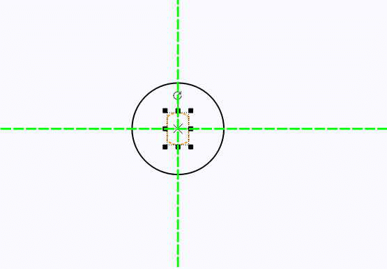
(2) Using the Selection Tool, drag the “TT Motor Shaft Hole” pattern from the “Open-Source Robot Hardware” library onto the “Circular Spacer” graphic. Align the “TT Motor Shaft Hole” vertically and horizontally centered with the “Circular Spacer” using alignment guides. As shown in the following figure.
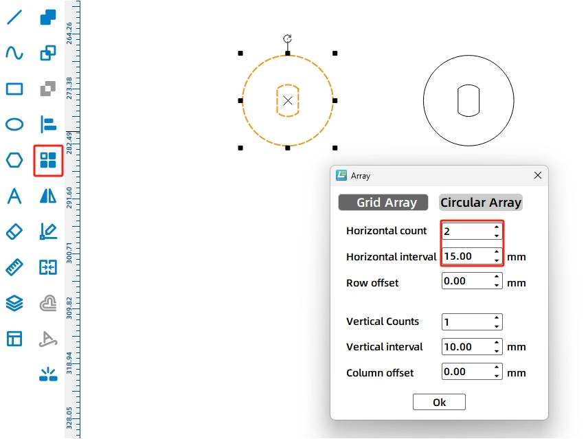
(3) Then, replicate the second spacer using a rectangular array. Use the Rectangular Array Tool to array the aligned circular spacer with 2 horizontal counts, 5mm horizontal spacing, 0mm offset between rows, and 1 vertical count. As shown in the following figure.
- Drawing the Box Base
In previous sections, we learned about the One-Click Fabrication tool. In this project, we will use this tool to design the box base for the amusement park advertising sign. Its function is to fix the motor, support the reciprocating mechanism for left-right sliding, and house the batteries and receiver.
(1) Click on the “One-Click Fabrication Tool” in the menu toolbar and select the “Rectangular Box” function. In the parameter settings window, set the box dimensions to “Length: 125mm, Width: 85mm, Height: 85mm” with “External Dimensions” selected. Set the groove (mortise) size to 21.2mm, material thickness to 3mm, and laser compensation to 0.2mm for a more secure fit when assembling. Finally, click “OK” to generate a set of boxes, as shown in the following figure.
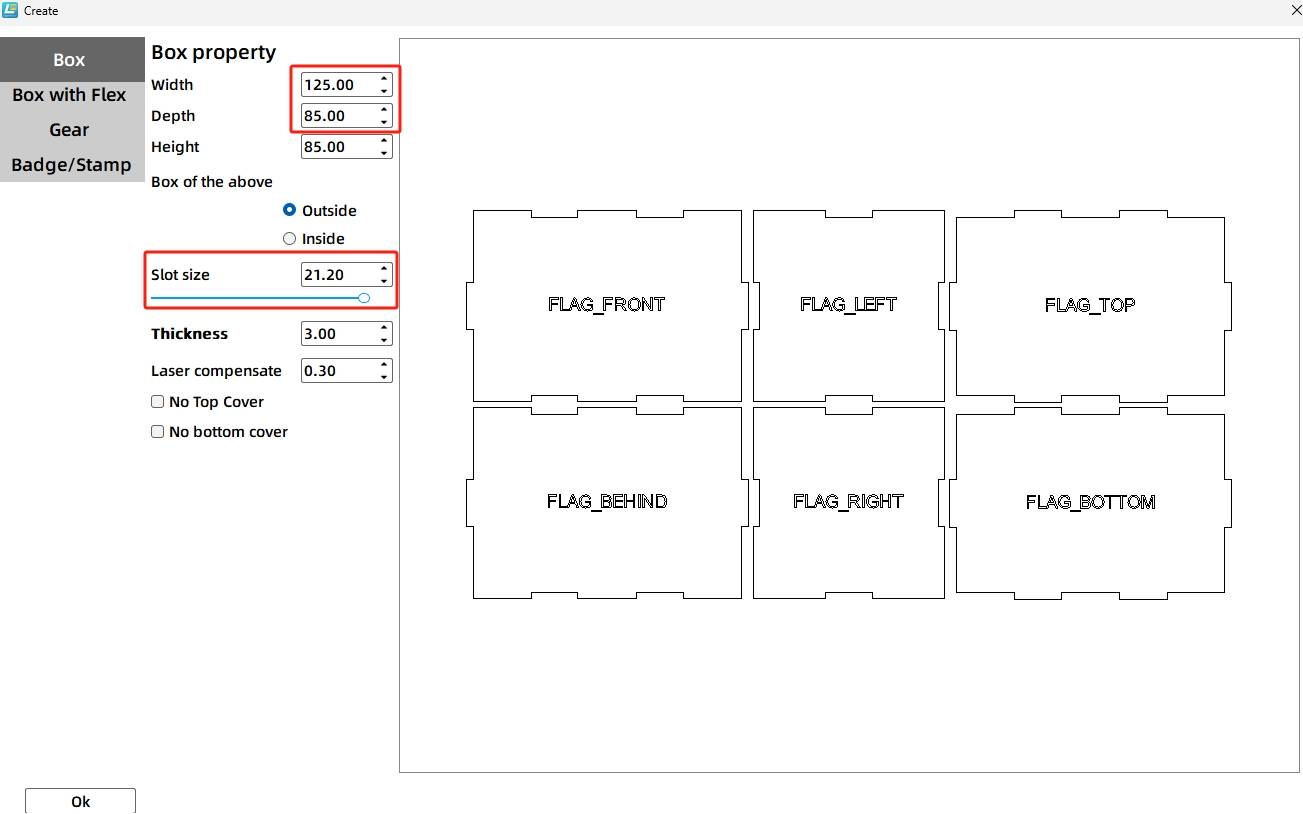
Next, we need to add a TT motor shaft hole to the “front” panel of the box. We can draw a circle of the same size as the motor shaft hole to assist in positioning.
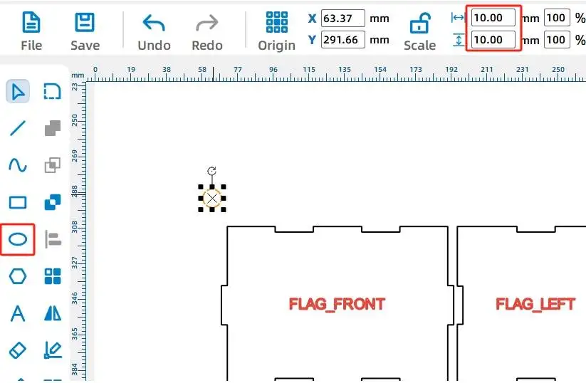
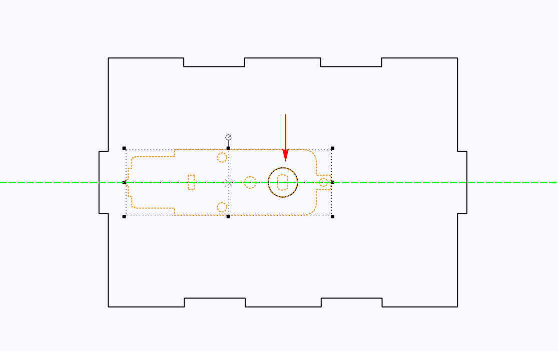
(2) Use the Selection Tool to drag the box panel with the “front” label to an empty area on the canvas. Then, use the Ellipse Tool to draw a circle with a width and height of 10mm. As shown in the following figure.
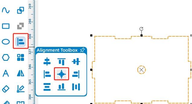
(3) Use the Selection Tool to select the box’s “front” panel and the circle. Align the circle horizontally and vertically centered on the “front” panel using the Alignment Toolbox. Then, delete the “front” label. As shown in the following figure.
(4) To add the TT motor to the “front” panel, drag the “OSROBOT Motor” graphic from the “Open-Source Robot” library onto the “front” panel graphic, ensuring that the circular shaft hole aligns perfectly with the 10mm diameter circle on the box’s “front” panel. As shown in the following figure.
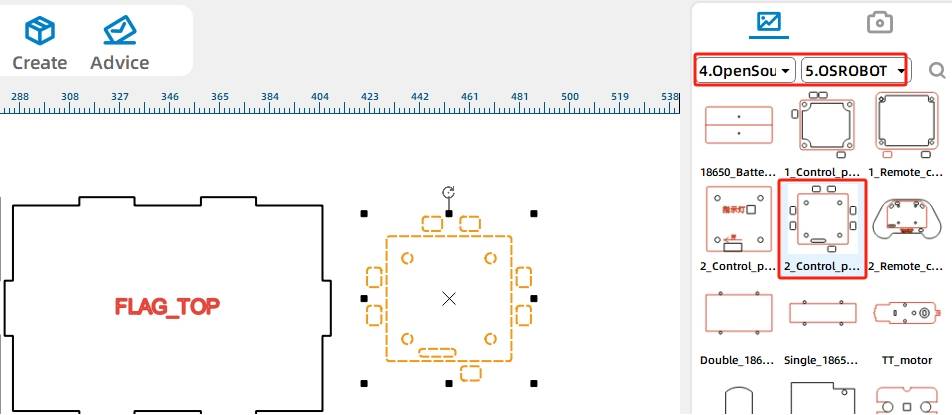
(5) Next, add the receiver hole to the “top” panel graphic. Use the Selection Tool to drag the box panel graphic with the “top” label. From the “Open-Source Robot” library, drag the “2.0 Control Board External” graphic and group it with the receiver board graphic. As shown in the following figure.
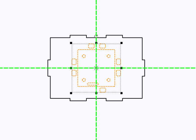
(6) Using the Selection Tool, select the “2.0 Control Board External” graphic and drag it into the “Top” panel graphic. Align the “2.0 Control Board External” with the “Top” panel using the alignment guides for vertical and horizontal centering. As shown in the following figure.
Next, we need to add holes for the reciprocating mechanism’s sliding rods on both sides of the box. Since the sliding rod is a flat wooden board with a height of 10mm, the holes in the box should be slightly larger than that, with a width of 3mm, the thickness of the board. As shown in the following figure.
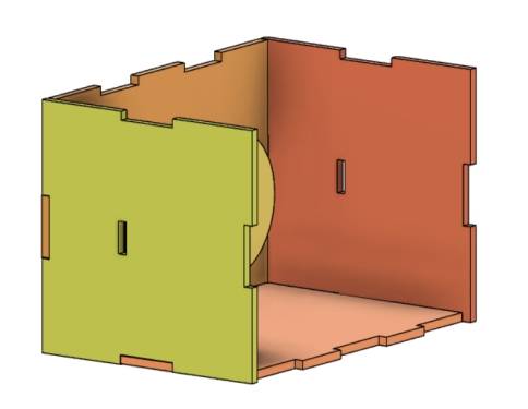
(7) Use the Selection Tool to drag out the box panel graphic with the “left” label. Then, use the Rectangle Tool to draw a rectangle with a “width of 3mm and height of 11mm.” As shown in the following figure.
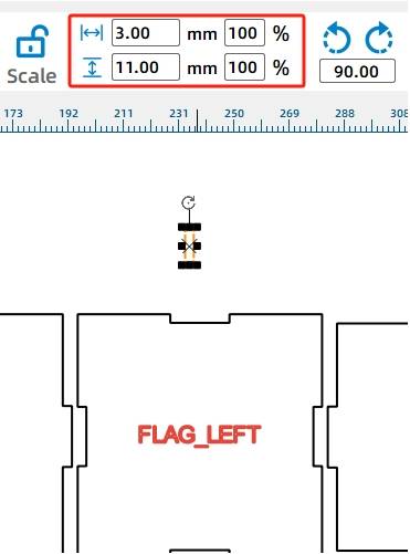
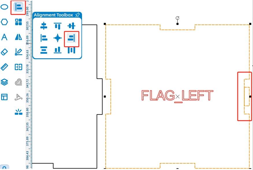
To accurately determine the position of the sliding rod hole in the “left” wooden panel, we first align the graphics and then, after actual measurement, use the X-axis coordinate subtraction method to move the sliding rod hole.
(8) Use the Selection Tool to select the box’s “left” panel and the rectangle with “width of 3mm and height of 11mm.” Align them using the Alignment Toolbox’s “Align Right” and “Vertical Center Alignment,” and delete the “left” label. As shown in
(9) Use the Selection Tool to select the small rectangle on the rightmost side and enter “-31” in the “X” axis box in the menu toolbar to move the small rectangle 31mm to the left. As shown in the following figure.
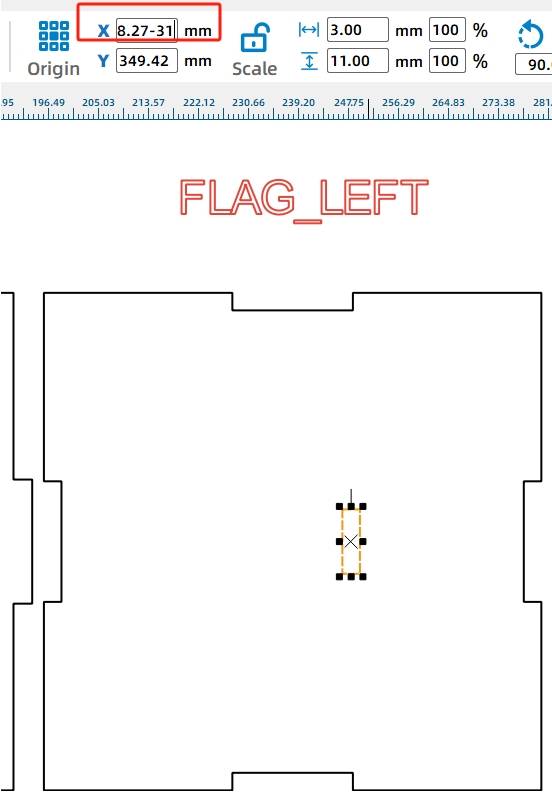
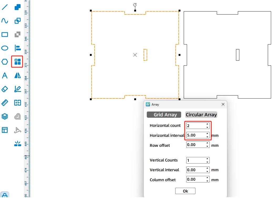
After designing the hole position on the left wood panel, we can replicate the process on the right wood panel using a rectangular array.
(10) Select the drawn graphics from the previous figure and use the Rectangular Array Tool with 2 horizontal instances, a horizontal spacing of 5mm, no row offset, and 1 vertical instance. As shown in the following figure.
The design drawings for the amusement park billboard are now complete. Next, we’ll proceed with the layout of the final drawings, as shown in the following figure.
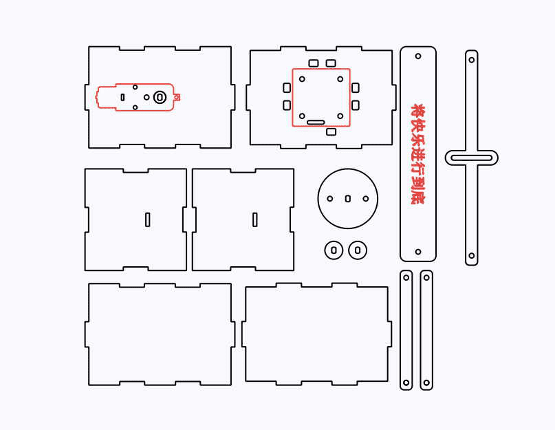
Laser Processing
After the drawing design is completed, we can set up the processing parameters to begin cutting.
Setting Parameters
(1) Outlining
Double-click the red block in the processing parameters area. For the material, select 1. Basswood Plywood. For the processing technique, select Outlining. Set the cutting depth to 0.10 and click OK.
(2) Cutting
Double-click the black block in the processing parameters area. For the material, select 1. Basswood Plywood again. For the processing technique, select Cutting. Set the cutting depth to 3.00 and click OK.
Starting the Fabrication
Turn on the power switch of the laser cutting machine and turn on the laser. Wait until the “Start Fabrication” button turns blue, then click it. Once the drawing is uploaded to the laser cutting machine, press the Start button on the laser cutting machine’s panel to begin cutting.
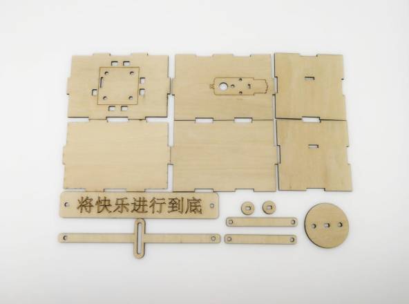
Model Assembly
After obtaining the parts of the amusement park billboard, let’s proceed with the model assembly.
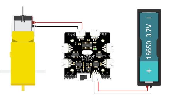
Circuit Wiring
Once the model assembly is complete, we need to connect the circuits according to the wiring diagram below. This will allow the amusement park billboard to rock. As shown in the following figure.
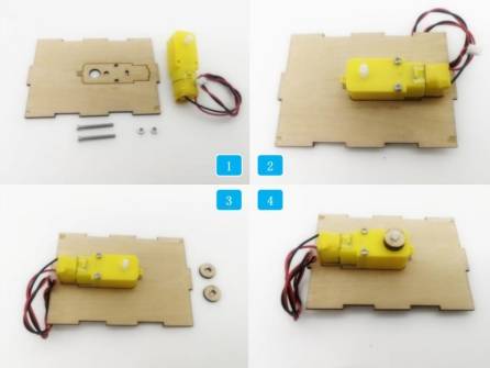
Structural Assembly
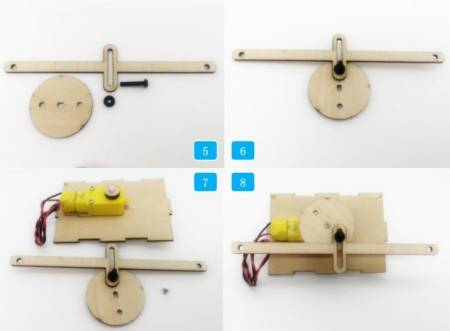
Step 1: Locate the TT motor, the wooden board for fixing the motor, and the M3 screws and nuts.
Step 2: Use the screws and nuts to install the TT motor onto the wooden board.
Step 3: Find two 15mm diameter circular spacers.
Step 4: Install the two spacers onto the shaft of the TT motor.
Step 5: Locate the M4 screw, M4 gasket, sliding rod, and a 50mm diameter disc (the nut will automatically tighten and lock the anti-rotation groove during circular motion, so a gasket is used instead).
Step 6: Use the screw to connect the anti-rotation groove with one of the eccentric holes of the disc, thus forming a reciprocating mechanism.
Step 7: Find an M2 self-tapping screw and the structure assembled in steps 4 and 6.
Step 8: Use the M2 self-tapping screw to secure the disc onto the TT motor.
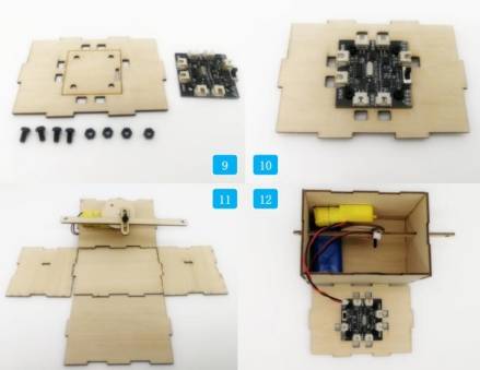
Step 9: Locate the M4 screw, nut, receiver, and the wooden board for fixing the receiver.
Step 10: Use the screw to secure the receiver onto the wooden board.
Step 11: Find the remaining five wooden boards for the cube box.
Step 12: Insert the sliding rod into the rectangular holes on both side boards first. Then assemble the five boards together. Finally, connect the wires according to the wiring diagram in the following figure.
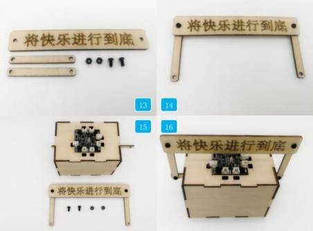
Step 13: Locate the M4 screw, nut, billboard, and support pole.
Step 14: Use the screw and nut to attach the support pole to the billboard.
Step 15: Install the top panel of the box and locate the billboard, M4 screw, and nut.
Step 16: Use the screw and nut to secure the billboard to the sliding rod of the box.
Summary
With this, the amusement park billboard is complete. This project combines the basic drawing techniques of LaserMaker introduced in previous chapters, focusing more on the use of tools such as measurement, X-axis calculations, angle rotation, and union operations, as shown in the above figure.
Most importantly, it demonstrates how to apply these tools to create a non-rotating yoke that enables reciprocating motion. Through the design and construction of this project, students will learn how to convert circular motion into reciprocating motion structures.
The task of distributing souvenir tokens at amusement parks also utilizes a reciprocating mechanism. Let’s explore how it is implemented.
Thought Extension
Where else in our daily lives do we see the use of non-rotating yoke structures? What other projects could we apply these structures to? Let’s use our imagination and brainstorm some ideas.
Browse Thunder Laser
Bolt >



.png) International
International
 United States
 Brasil
 Canada
 Costa Rica
 Mexico
 Česká
Česká
 Romania
 Polska
 Ireland
 Portugal
 Lietuva
 Россия
 Deutschland
 Britain
 Україна
 France
 Sverige
 Italia
 Norway
 Denmark
 Ελλάδα
 한국
한국
 中国
中国
 ประเทศไทย
 中国香港
中国香港
 Israel
 中國臺灣
中國臺灣
 India
India
 پاکستان
 پශ්රී ලංකා
 ジャパン
ジャパン
 Australia
 New Zealand
 South Africa